II-16
2.3.2
Solder Points
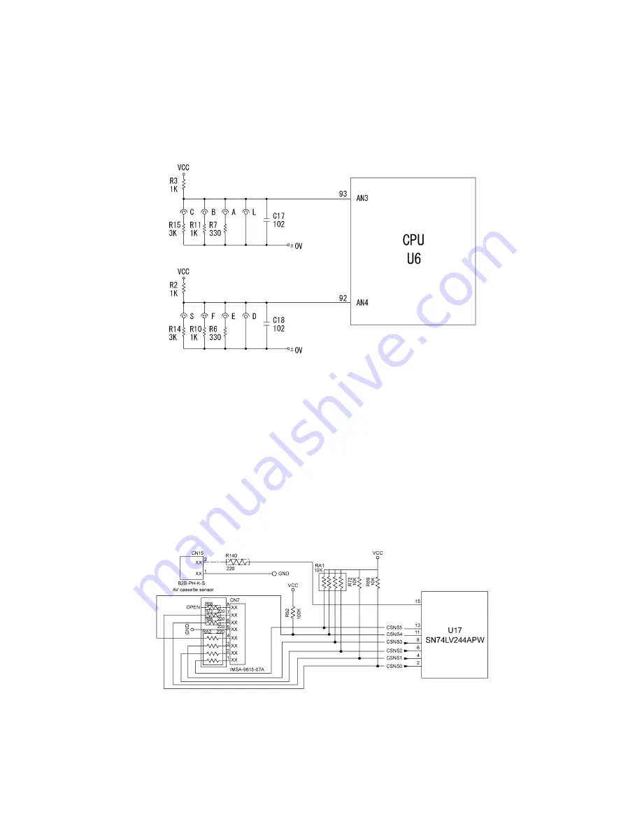
Fig. 2.3-3 shows the solder point circuit. One of solder points from L to S is soldered according to the
resistance level of the thermal head.
When the solder point is changed, verify with a multi meter whether solder on the unsolder point is
removed properly.
Caution: Be sure to use the lead-free solder.
Fig. 2.3-3 Solder Point Circuit
2.3.3
Cassette Sensor & AV Cassette Sensor Circuit
The sensor circuit consists of a 6-switch cassette sensor (CSNS0 through CSNS5) and AV cassette
sensor (AVSW).
Loading a tape cassette turns on some of those five switches on the cassette sensor while keeping
other switches off depending upon the ID encoding holes provided in the tape cassette currently
loaded. If an encoding ID hole is closed, the corresponding sensor switch goes on.
The AV cassette sensor (AVSW) is provided for distinguishing AV labels cassettes from TZ
cassettes.
With the states of those sensor switches, the CPU identifies the tape width, ink ribbon type of the
tape cassette, and TZ/AV type, as listed in Table 3.1-1.
Fig 2.3-4 shows the cassette sensor and AV cassette sensor circuit.
Fig. 2.3-4 Cassette Sensor and AV Cassette Sensor Circuit
Содержание PT-9500PC - P-Touch 9500pc B/W Thermal Transfer Printer
Страница 1: ...SERVICE MANUAL MODEL PT 9500PC ...
Страница 2: ...SERVICE MANUAL MODEL PT 9500PC ...
Страница 86: ...IV 10 3 The LED does not turn on 4 No printing is performed ...
Страница 87: ...IV 11 5 The interface malfunction 6 The tape is not cut ...
Страница 88: ...IV 12 7 The tape is not fed correctly ...
Страница 89: ...IV 13 ...
Страница 90: ...IV 14 8 Half cut failure ...
Страница 91: ...IV 15 9 Forced tape eject failure ...
Страница 92: ...IV 16 10 The failure of pressure contact release of the roller holder ...
Страница 103: ......
Страница 104: ......
Страница 105: ......
Страница 106: ...Sep 2003 8V2054BE0 Printed in Japan ...


