


II-12
2.2
OUTLINE OF CONTROL ELECTRONICS
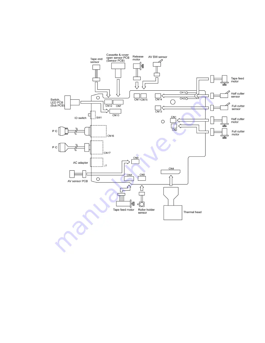
Fig. 2.2-1 shows the block diagram of the control electronics. The control electronics consist of the
following components.
Fig. 2.2-1 Block Diagram of the Control Electronics
2.2.1
Main PCB
This manages all the components. This PCB consists of CPU, ROM, RAM, EEPROM, serial IF
driver, USB chip and motor drivers etc.
2.2.2
Cassette & Cover Open Sensor PCB (Sensor PCB)
This PCB has sensors to detect tape width in a cassette and a type of ink ribbon, and the cassette
cover open sensor (mechanical SW).
2.2.3
Tape End Sensor PCB
This is the sensor to read the tape end pattern (zebra pattern), using the photo interrupter.
Содержание PT-9500PC - P-Touch 9500pc B/W Thermal Transfer Printer
Страница 1: ...SERVICE MANUAL MODEL PT 9500PC ...
Страница 2: ...SERVICE MANUAL MODEL PT 9500PC ...
Страница 86: ...IV 10 3 The LED does not turn on 4 No printing is performed ...
Страница 87: ...IV 11 5 The interface malfunction 6 The tape is not cut ...
Страница 88: ...IV 12 7 The tape is not fed correctly ...
Страница 89: ...IV 13 ...
Страница 90: ...IV 14 8 Half cut failure ...
Страница 91: ...IV 15 9 Forced tape eject failure ...
Страница 92: ...IV 16 10 The failure of pressure contact release of the roller holder ...
Страница 103: ......
Страница 104: ......
Страница 105: ......
Страница 106: ...Sep 2003 8V2054BE0 Printed in Japan ...