background image

II-9

   [ 2 ]

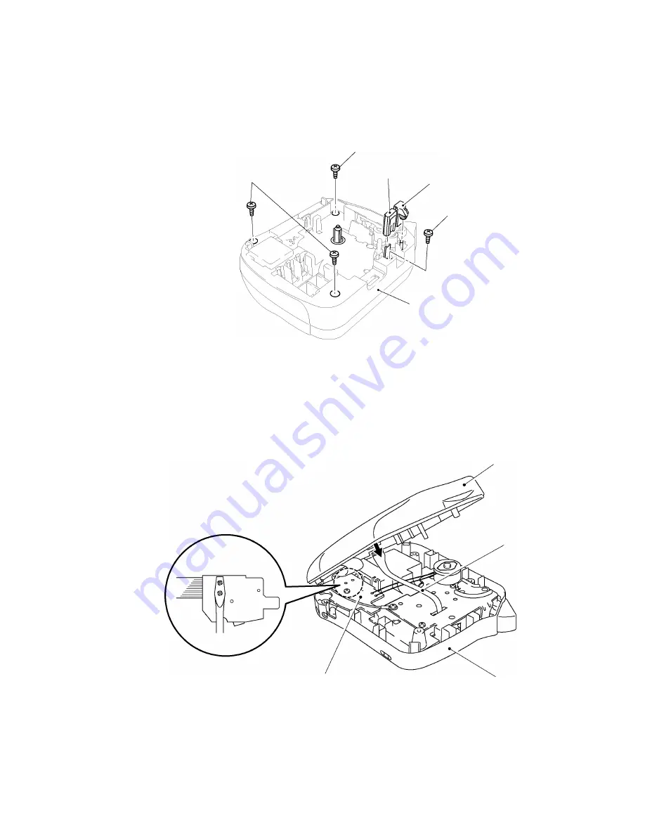
Removing the bottom cover, the cutter case ASSY and the board

(1)

Place the machine upside down.

(2)

Pull out the cutter case ASSY and the board from the frame.

(3)

Remove the four screws, then the bottom cover and the upper cover are able to be
separated.

Fig. 2.2-3  Removing the Bottom Cover, Cutter Case ASSY and the Board (1)

(4)

Open the upper cover to the left as shown below.

(5)

Discharge the condenser (C1) on the sub PCB ASSY with tool like a screwdriver.

(6)

Disconnect the thermal head flat cable from the main PCB.

Note:  Discharge without fail before disconnecting the thermal flat cable, otherwise the electronic

part such as LSI or others should be damaged.

Fig. 2.2-4  Removing the Bottom Cover, Cutter Case ASSY and the Board (2)

Screw

Cutter case ASSY

Board

Screw

Screws

Bottom cover

Upper cover

Sub PCB

Bottom cover

Thermal head flat cable

Содержание P-touch PT-1100

Страница 1: ...P touch SERVICE MANUAL MODEL PT 1100 1130 1170 1180 11Q PT 1250 1160 ST 1150 Heavy Duty LabelerTM REVISED 1 ...

Страница 2: ...SERVICE MANUAL MODEL PT 1100 1130 1170 1180 11Q PT 1250 1160 ST 1150 Heavy Duty LabelerTM ...

Страница 3: ...ht Brother 2002 All rights reserved No part of this publication may be reproduced in any form or by any means without permission in writing from the publisher Specifications are subject to change without notice ...

Страница 4: ...er concerned persons to accurately and quickly provide after sale service for our PT 1100 1130 1170 1180 11Q PT 1250 1160 and ST 1150 To perform appropriate maintenance so that the machine is always in best condition for the customer the service personnel must adequately understand and apply this manual This manual is made up of three chapters and appendices CHAPTER I SPECIFICATIONS CHAPTER II MEC...

Страница 5: ...CHAPTER I SPECIFICATIONS ...

Страница 6: ...nal Appearance I 1 1 1 2 Keyboard I 1 1 1 3 Display I 2 1 1 4 Printing Mechanism I 2 1 1 5 Tape Cassette I 2 1 1 6 Tape Cutter I 2 1 2 ELECTRONICS SPECIFICATIONS I 6 1 2 1 Character Generator I 6 1 2 2 Power Supply I 6 1 3 SPECIAL KEY I 6 1 3 1 Format I 6 1 3 2 Demonstration Print I 6 ...

Страница 7: ...g Weight g Carton with One Unit 670g Clamshell 650g Carrying Case 1300g including the machine packing materials and packaged standard components 1 1 2 Keyboard 1 Entry system Rubber 41 key PT 1100 1130 1170 1180 11Q ST 1150 Rubber 40 key and tact switch PT 1250 1160 2 Number of alphanumeric 30 and symbol keys 3 Number of function keys 11 PT 1100 1130 1170 1180 11Q ST 1150 10 PT 1250 1160 including...

Страница 8: ...t H2 2 26 x 5 92 mm 16 x 42 dot Double width and double height 4 4 37 x 5 92 mm 31 x 42 dot Quadruple width and double height 8 8 74 x 5 92 mm 62 x 42 dot This part explains the dot size of H character as an example in the table above because the character size is different by the width of the tape and the character 1 1 5 Tape Cassette 1 Cassette Cartridge type TZ cassette 2 Types of tape cassette...

Страница 9: ...I 3 Fig 1 1 2 Key Arrangement 1 ...

Страница 10: ...I 4 Fig 1 1 2 Key Arrangement 2 ...

Страница 11: ...I 5 Fig 1 1 2 Key Arrangement 3 ...

Страница 12: ...wn the power 2 If it drops even more below approx 5 3V the CPU displays the message to warn you of a low battery after completion of printing 3 If it drops even more below approx 5 0V the CPU interrupts the printing and displays the message to warn you of a very low battery 4 If it drops below approx 4 8V the CPU immediately shuts down the power Displays different for each country when the battery...

Страница 13: ...CHAPTER II MECHANISMS ...

Страница 14: ...ard II 9 3 Removing the frame ASSY II 10 4 Removing the terminal press cover II 13 5 Removing the battery terminals II 14 6 Removing the sub PCB II 15 7 Removing the main PCB and the rubber 41 key PT 1100 1130 1170 1180 11Q ST 1150 II 16 8 Removing the main PCB the rubber 40 key and the jog dial PT 1250 1160 II 17 2 2 2 Reassembly Procedure II 18 1 Installing the rubber 41 key and main PCB PT 1100...

Страница 15: ...and final check II 27 2 3 TROUBLESHOOTING II 33 2 3 1 Precautions II 33 2 3 2 After Repairing II 33 2 3 3 Error Message Display II 34 2 3 4 Troubleshooting Flows II 35 1 Tape feeding failure II 35 2 Printing failure II 37 3 Powering failure Nothing appears on the LCD II 39 4 No key entry possible II 40 ...

Страница 16: ...mal film tape cassettes If the selected heating element s generates heat the ink on the sandwiched ribbon will be melted and transferred to the tape producing a dot s on the tape The ink ribbon and the tape are advanced and then the next heating cycle is repeated thus forming a character on the tape For non laminated thermal film tape cassettes If the selected heating element s generates heat the ...

Страница 17: ...pper and lower Also the tape feed sub roller is pressed perpendicularly against the tape feed roller built in the tape cassette with the tape the laminate tape and adhesive base tape when using laminated tape cassettes sandwiched inbetween by the roller holder springs upper and lower and at the same time the tape feed sub roller gear becomes engaged with the tape idle gear Opening the cassette cov...

Страница 18: ...sub roller Accordingly the sandwiched tape and ink ribbon will be advanced When a laminated tape cassette is mounted the sandwiched laminate tape adhesive base tape and ink ribbon will be advanced together The feeding amount of the platen is slightly less than that of the tape feed sub roller Fig 2 1 3 Tape Feeding Mechanism DC motor Platen roller Frame Thermal head ASSY Roller holder ASSY Tape id...

Страница 19: ...ibbon drive cam the ribbon take up roll in the tape cassette also rotates to take up the ink ribbon To apply proper tension to the ink ribbon between the platen roller and the ribbon drive cam the feed amount of the ribbon drive cam is slightly greater than that of the platen idle gear The difference between the tape feed speeds at the platen roller and at the ribbon drive cam is absorbed by the c...

Страница 20: ...d printing is fed out from the tape cassette and stops at a point passed between the cutter case ASSY and the board When the cutter lever is pushed at this point then the cutter case ASSY cutter blade is operated to cut tape Fig 2 1 5 Tape Cutter Mechanism Cutter blade Board Cutter lever Cutter case ASSY Tape cassette ...

Страница 21: ...s Closing the cassette cover ASSY pivots the roller holder ASSY towards the thermal head so that the cutter lever stopper does not interfere with the cutter lever When a tape cassette is loaded its outer edge pushes the tab of the roller holder ASSY to pivot the roller holder ASSY towards the thermal haed so that the cutter lever stopper does not interfere with the cutter lever Fig 2 1 6 Cutter Sa...

Страница 22: ... backside pushes the thermal head at roller holder ASSY by pressing A surface of the roller holder ASSY Fig 2 1 8 Holder Cam Cassette Cover ASSY and Roller Holder ASSY Fig 2 1 9 Interlock Mechanism of the Roller Holder Thermal head Platen roller Tape cassette Holder cam Cassette cover ASSY A Roller holder release spring A Tape feed sub roller Shaft Roller holder ASSY Holder cam Cassette cover ASSY...

Страница 23: ...r ASSY to the direction of the arrow to remove the holder cam from the cassette cover ASSY Caution Never draw out the holder cam The rib B on the holder cam may be damaged 4 The cassette cover is removed by applying a force toward D direction of the arrow by pushing the C section outward 5 Remove the tape cassette 6 Remove the batteries Fig 2 2 1 Removing the Cassette Cover Fig 2 2 2 Removing the ...

Страница 24: ...oard 1 4 Open the upper cover to the left as shown below 5 Discharge the condenser C1 on the sub PCB ASSY with tool like a screwdriver 6 Disconnect the thermal head flat cable from the main PCB Note Discharge without fail before disconnecting the thermal flat cable otherwise the electronic part such as LSI or others should be damaged Fig 2 2 4 Removing the Bottom Cover Cutter Case ASSY and the Boa...

Страница 25: ...r 2 Remove the three screws and remove the frame ASSY from the bottom cover Note The cutter lever will be disconnected from the cutter lever shaft of the frame Assy at this point Fig 2 2 5 Removing the Frame ASSY FG harness Screws Bottom cover Frame ASSY Melting the solder Upper cover Melting the solder ...

Страница 26: ...II 11 Disassembling the Frame ASSY Removing the DC motor ASSY 1 Remove the two screws from the frame ASSY and take out the motor ASSY Fig 2 2 6 Removing the DC Motor ASSY DC motor ASSY Screws Frame ASSY ...

Страница 27: ...er taking off the retaining ring remove the roller holder ASSY and the roller holder return spring from the frame ASSY 2 Remove a screw which secures the thermal head ASSY to the frame ASSY then take out the thermal head ASSY Fig 2 2 7 Removing the Roller Holder ASSY Fig 2 2 8 Removing the Thermal Head Roller holder release spring Roller holder ASSY Retaining ring Frame ASSY Screw Frame ASSY Therm...

Страница 28: ...bottom cover You can remove the terminal press cover by releasing the two hooks from the back side of the bottom cover by using tool like a flat screwdriver 2 Remove the battery terminal from the terminal press cover Fig 2 2 9 Removing the Terminal Press Cover Terminal press cover Bottom cover Groove Hooks Battery terminal ...

Страница 29: ...from the bottom cover Fig 2 2 10 Removing the Battery Terminals 1 3 Place the bottom cover upside down After disengaging the hooks in A section of the battery terminal A by using tool like a flat screwdriver remove the battery terminal A from the bottom cover Fig 2 2 11 Removing the Battery Terminals 2 Battery terminal B Bottom cover Battery terminal Hook Battery terminal Battery terminal A A Bott...

Страница 30: ...PCB Note The AC jack is not provided on the sub PCB for PT 1180 Therefore the form of the bottom cover is slightly different from the figure below 2 The relay harness soldered to the sub PCB is removed Fig 2 2 12 Removing the Sub PCB Screw Sub PCB AC jack Soldering Battery terminal Relay harness Bottom cover Battery terminal ...

Страница 31: ...portion of the machine to discharge static electricity or the LSI and other electronic devices should be damaged due to the electricity charged in your body Note2 The LCD is removed by opening the hook section wide toward direction indicated by arrow A Fig 2 2 13 Removing the Main PCB Fig 2 2 14 Removing the Rubber 41 Key A LCD Hook Upper cover Main PCB Rubber 49 key Screws Screws Rubber 41 key Up...

Страница 32: ...ion of the machine to discharge static electricity or the LSI and other electronic devices should be damaged due to the electricity charged in your body Note2 The LCD is removed by opening the hook section wide toward direction indicated by arrow A Fig 2 2 15 Removing the Main PCB and the Jog Dial Fig 2 2 16 Removing the Rubber 40 Key A LCD Hook Upper cover Main PCB Rubber 40 key Jog dial Upper co...

Страница 33: ...tted into the nine boss provided on the upper cover 2 Check that there is no foreign material or dust on the key contacts of the main PCB then install the PCB The LCD is installed first on the upper cover 3 Tighten the four screws for securing the PCB Tightening torque 0 29 N m 3 kg cm Fig 2 2 17 Installing the Rubber 41 Key and Main PCB Screws Upper cover Boss Main PCB Rubber 41 key Screws ...

Страница 34: ...dial set on the upper cover 3 Check that there is no foreign material or dust on the key contacts of the main PCB then install the PCB The LCD is installed first on the upper cover 4 After matched the jog dial and the main PCB tighten the four screws for securing the PCB Tightening torque 0 29 N m 3 kg cm Fig 2 2 18 Installing the Rubber 40 Key and the Main PCB Screws Upper cover Jog dial Boss Mai...

Страница 35: ...om cover certainly and moves up and down freely Tightening torque 0 29 N m 3 kg cm Note1 Make sure that the battery terminal does not run on the VR1 Note2 The AC jack is not provided for PT 1180 Therefore the form of the bottom cover is slightly different from the figure below and the AC jack groove is also not provided Fig 2 2 19 Installing the Sub PCB Fig 2 2 20 Details of Battry Terminal Screw ...

Страница 36: ... terminals completely Note2 Fit the battery terminal firmly at the bottom Further make sure that the battery terminal does not contact with the battery terminals B Fig 2 2 21 Installing the Battery Terminals 5 Installing the terminal press cover 1 Install the battery terminal to the terminal press cover as shown below 2 Push the terminal press cover along the groove of the bottom cover until the t...

Страница 37: ...is secured to the frame Assy at this point with screws of A Note Install the frame ASSY so that the FG harness terminal metallic section does not contact with sub PCB 5 Solder the motor harness to the sub PCB Note Be careful to the direction of the motor harness and not to stick out from the designated place when soldering Tightening torque 0 39 N m 4 kg cm Fig 2 2 23 Installing the Cutter Lever a...

Страница 38: ... the Thermal Head ASSY 2 Set the release spring onto the frame ASSY so that its straight end a is fitted to the section A on the roller holder ASSY then install them to the frame so that the spring bent end b becomes hooked on the section B And then set the retaining ring securely Fig 2 2 25 Installing the Roller Holder ASSY Screw Fit for boss Thermal head ASSY Frame ASSY B b a A Roller holder ASS...

Страница 39: ...hten the DC motor to the frame ASSY with the two screws Be careful to the direction of the motor harnesses Tightening torque 0 10 0 20 N m 1 2 kg cm Backlash of DC motor 0 05 0 2 mm Fig 2 2 26 Installing the DC Motor ASSY DC motor ASSY Screws ...

Страница 40: ...ver 1 2 Place the upper and bottom cover upside down And secure the bottom cover by four screws Tightening torque 0 39 N m 4 kg cm 3 The cutter case ASSY and board are inserted into the frame ASSY Note When setting the bottom cover with upper cover care must be taken so that the cable and harness are not caught between them Fig 2 2 28 Installing the Bottom Cover 2 Bottom cover Thermal head flat ca...

Страница 41: ...m to the cassette cover Caution1 Insert the holder cam into the cassette cover correctly Check that the holder cam is not removed easily Caution2 After checking that the D section on the cassette cover is not deteriorated or damaged install the holder cam into the cassette cover 3 Load the tape cassette 4 Put the batteries in the bottom cover Fig 2 2 30 Installing the Tape Cassette the Batteries a...

Страница 42: ...irm the On Off key 9 At last no problem is verified by conducting the following inspections 9 1 Inspection Mode Starting Procedure The inspection mode is initiated by pressing the CODE key K key and On Off key simultaneously when internal RAM is cleared while electrical power OFF Displays will become as shown in Fig 2 First release the On Off key However Error processing will be started when occur...

Страница 43: ...e soldering 9 2 1 2 Head Rank Display The head rank displays the rank as designated by the solder points A C The rank B is defined as the setting for no soldering Country Specification LCD Display Solder Points A B C B 0 H H H B H L H A A L H H C C H H L L indicates the soldering 9 2 1 3 Power Supply Voltage Check Display Inspection voltage 7 5 0 2 V Displays when within the required input voltage...

Страница 44: ...tch with the finger tip while checking ON OFF display Shifts to the Key Inspection Mode when depressed key Fig 9 Display 9 2 3 Key Inspection Mode 3 Key Here check the key input function Display of Fig 9 is indicated when depressed key or depressed 3 key in the display of Fig 8 except while in the Key Inspection Mode Fig 9 Shifts to the Key Inspection Mode when depressed key Fig 10 Display The COD...

Страница 45: ...irection of the rotation After confirmation was made shifts to 9 2 4 CUT Mode when depressed key Fig 13 Display Fig 13 9 2 4 Cut Mode 4 Key Here check the cutter function Display of Fig 12 is indicated when depressed key or depressed 4 key in the display of Fig 13 except while in the Key Inspection Mode Fig 14 Fig 15 is displayed when depressed key to feed the tape 1 is displayed after completed t...

Страница 46: ...printing is started when depressed key Fig 18 Display Initialize all memory after completed the printing and turns the electrical power to off After finishing to print cut the printed tape and check that it is 79 4 mm tape length and 50 2 4 2 5 mm printed letter length 9 2 6 PRINT 2 Mode 6 Key Performs the same printing as PRINT 1 My be omitted when PRINT 1 is confirmed being correct Fig 19 is dis...

Страница 47: ...When you failed peel off the yellow volume VR1 by the cassette sensor switch actuators as shown below And insert a screwdriver to adjust the length of the tape by rotating a trimmer If rotating the trimmer to the right CW the length becomens short If rotating to the left CCW it becomes long After the adjustment verify the tape length and printed letter length by performing the PRINT 1 or PRINT 2 f...

Страница 48: ...n them 2 When supplying power to the PT 1100 1130 1170 1180 11Q PT 1250 1160 and ST 1150 having problems from either a set of batteries or the AC adapter excluding PT 1180 make sure that its output voltage level is 8 to 10V under no load 3 When supplying power from a stabilized power unit use the power unit with approx 3A capacity and choose the output level of 7 to 10V When connecting it to the P...

Страница 49: ... the message Function Selection Mode SET key depressed when selected repeat or numbering while no data in the text buffer SET key depressed when no letter on the cursor or when tried numbering while no numeral on the cursor Number of Copy Setting Mode SET key depressed when no cassette installed SET key depressed when text vertical size is larger than the installed tape width SET key depressed whe...

Страница 50: ...35 II 2 3 4 Troubleshooting Flows 1 Tape feeding failure ...

Страница 51: ...36 II ...

Страница 52: ...37 II 2 Printing failure ...

Страница 53: ...38 II ...

Страница 54: ...39 II 3 Powering failure Nothing appears on the LCD ...

Страница 55: ...40 II 4 No key entry possible ...

Страница 56: ...CHAPTER III ELECTRONICS ...

Страница 57: ...s matrix III 4 2 Solder points III 5 3 Jog Dial Only for PT 1250 1160 III 6 3 2 4 On Off Key Reset Circuit and Power Saving Circuit III 7 1 Power On Off circuit III 7 2 Power saving circuit III 8 3 2 5 Motor Control Circuit III 9 3 2 6 Thermal Head Drive Circuit III 10 3 2 7 Voltage Detection Circuit and Temperature Sensor circuit III 11 1 Voltage detection circuit III 11 2 Ambient temperature sen...

Страница 58: ...epairing III 16 3 3 3 Troubleshooting Flows III 17 1 Tape feeding failure III 17 2 Printing failure III 17 3 Powering failure Nothing appears on the LCD III 18 4 Abnormal LCD indication III 19 5 No key entry possible III 20 6 Tape cassette type not identified III 20 ...

Страница 59: ...an LCD keyboard Jog dial PT 1250 1160 only and thermal head 3 1 3 Sub PCB Sub PCB consists of the sensor switches which identify the tape cassette type governor circuit which controls the rotation of DC motor AC adapter jack and battery terminal The AC jack is not provided for PT 1180 3 1 4 Motor DC motor feeds tape 3 1 5 Thermal Head This is a thick film thermal print head which integrates a heat...

Страница 60: ...ntacts matrix solder points specification switching over circuit and jog dial PT 1250 1160 only 3 Power On Off circuit and power saving circuit 4 Motor control circuit 5 Thermal head drive circuit 6 Voltage detection circuit and temperature sensor circuit 7 Oscillation circuit 8 Reset circuit 9 Power supply circuit 10 Cassette sensor circuit Fig 3 2 1 Main PCB Block Diagram ...

Страница 61: ...30A is a 8bit microprocessor produced by CMOS silicon gate process which integrates a 32 kilobyte ROM and a 1 5 kilobyte RAM The LCD driver SPLC 780 A2 is a LSI that drives the LCD in 1 8 duty and 1 4 bias level Fig 3 2 2 CPU CG ROM and LCD Drive ...

Страница 62: ...3 2 4 shows a timing chart and waveforms of key scanning by the CPU Ports P71 through P76 on the CPU produce a series of key scanning pulses Every scanning pulse is in low impedance for 1 ms while active and in high impedance while inactive Ports P60 through P67 act as input ports which receive key status The CPU scans the key contacts matrix every 10 ms If the CPU reads the same data on an input ...

Страница 63: ...160 and ST 1150 Specification PT 1250 PT 1160 PT 1100 1130 1170 1180 11Q ST 1150 Solder point MN101C30ABE MN101C30ABF1 MN101C30ABD No point solder UK German U S A Canada Australia Point 1 solder French Canada Point 2 solder Belgium Solder points A through D are reserved for the future use for the thermal head ranking The CPU reads the solder point status once in the powering on to confirm the spec...

Страница 64: ...G1 waveforms are varied by rotating the JOG dial The rotational directions are determined from the variation pattern of this two input signal waveforms JOG Switching Dial Signal Fig 3 2 6 Fig 3 2 7 Jog Dial Circuit CW JOG1 signal JOG0 signal JOG1 signal JOG0 signal CCW ...

Страница 65: ...r On Off circuit Fig 3 2 8 shows a circuit diagram of the power On Off key The CPU processes the On Off key state in a sequence quite different from other keys although the On Off key is on the same key pad Fig 3 2 8 On Off Key Circuit Fig 3 2 9 Powering On Off sequence ...

Страница 66: ... P11 high to cut off the Vcc which normally would feed power to the logic circuits except the CPU In this way the CPU enters the sleep mode where oscillation stops so as to feed no clock to the CPU In the sleep mode the 5BV feeds power only to the CPU To cancel the power saving mode automatic powering off mode and resume the normal operation mode press the power On Off key Fig 3 2 10 Power Saving ...

Страница 67: ...he CPU produces a start stop control signal to the motor control circuit Fig 3 2 12 shows the part of motor waveforms 1 BA6220 is electronic governor IC and controls to keep the rotation speed of motor constant even if the power source voltage VBT varies Fig 3 2 11 Motor Control Circuit Fig 3 2 12 Part of Motor Waveforms ...

Страница 68: ...of the thermal head according to the signal produced from P03 Fig 3 2 14 shows the timing chart of the thermal head drive Capacitor C12 works as a thermal head overheat protector It cuts off the P03 signal to shut down invalid drive current if the signal sticks to the low level due to any malfunctions of the programs or the CPU Since the thermal head is very sensitive to heat and the head drive so...

Страница 69: ...drive source voltage the CPU determines the optimum head drive power During non printing If the voltage level of the VAD drops below approx 6 8V the CPU immediately shuts down the power During printing If the voltage level of the VAD rises over approx 10 8V the CPU immediately shuts down the power If it drops even more below approx 5 3V the CPU displays the message to warn you of a low battery aft...

Страница 70: ...the resistance of the TH2 whose internal resistance varies depending upon the ambient temperature to the voltage variation and then feeds its output to the A D input port PA0 on the CPU According to the Ambient temperature data the CPU determines the optimum head drive power Fig 3 2 16 Ambient Temperature Sensor Circuit ...

Страница 71: ... shows the oscillation circuit This circuit contains an oscillator and generates an oscillation at 8 MHz which act as the CPU basic clock The CPU divides this into half 4 MHz to synchronize its internal operations Fig 3 2 17 Oscillation Circuit ...

Страница 72: ...4 is for the logic circuit capacitor C1 is for the thermal head and DC motor drive sources Connecting the AC adapter plug with the AC jack J1 cuts off the power fed from the batteries and feeds power from the AC adapter However the power for memory backup is fed from the battery Note1 The AC jack is not provided for PT 1180 Fig 3 2 19 shows the polarity of the AC adapter plug Fig 3 2 18 Power Supp...

Страница 73: ...provided on a tape cassette currently mounted By perceiving the states of those sensor switches the CPU identifies the tape cassette type the varieties and the widths If an ID hole is open the sensor switch is not pushed Table 3 2 1 lists the coded values for identifying the tape cassette type Fig 3 2 20 Cassette Sensor Circuit Table 3 2 1 Coded Values for Identifying Tape Cassette Type ...

Страница 74: ... the relationship between them 2 When supplying power to the PT 1100 1130 1170 1180 11Q PT 1250 1160 and ST 1150 having problems from either a set of batteries or the AC adapter make sure that its output voltage level is 8 to 10V under no load 3 When supplying power from a stabilized power unit use the power unit with approx 3A capacity and choose the output level of 7 to 9V When connecting it to ...

Страница 75: ...III 17 3 3 3 Troubleshooting Flows 1 Tape feeding failure 2 Printing failure ...

Страница 76: ...III 18 3 Powering failure Nothing appears on the LCD ...

Страница 77: ...III 19 4 Abnormal LCD indication ...

Страница 78: ...III 20 5 No key entry possible 6 Tape cassette type not identified ...

Страница 79: ...APPENDICES Circuit Diagrams A MAIN PCB CIR 1100 PT 1100 1130 1170 1180 11Q ST 1150 B MAIN PCB CIR 1250 PT 1250 1160 C SUB PCB CIR 1250 ...

Страница 80: ......

Страница 81: ......

Страница 82: ......

Страница 83: ...Jan 2002 8V2010BE1 Printed in Japan ...

Отзывы: