II-2
2.1.2
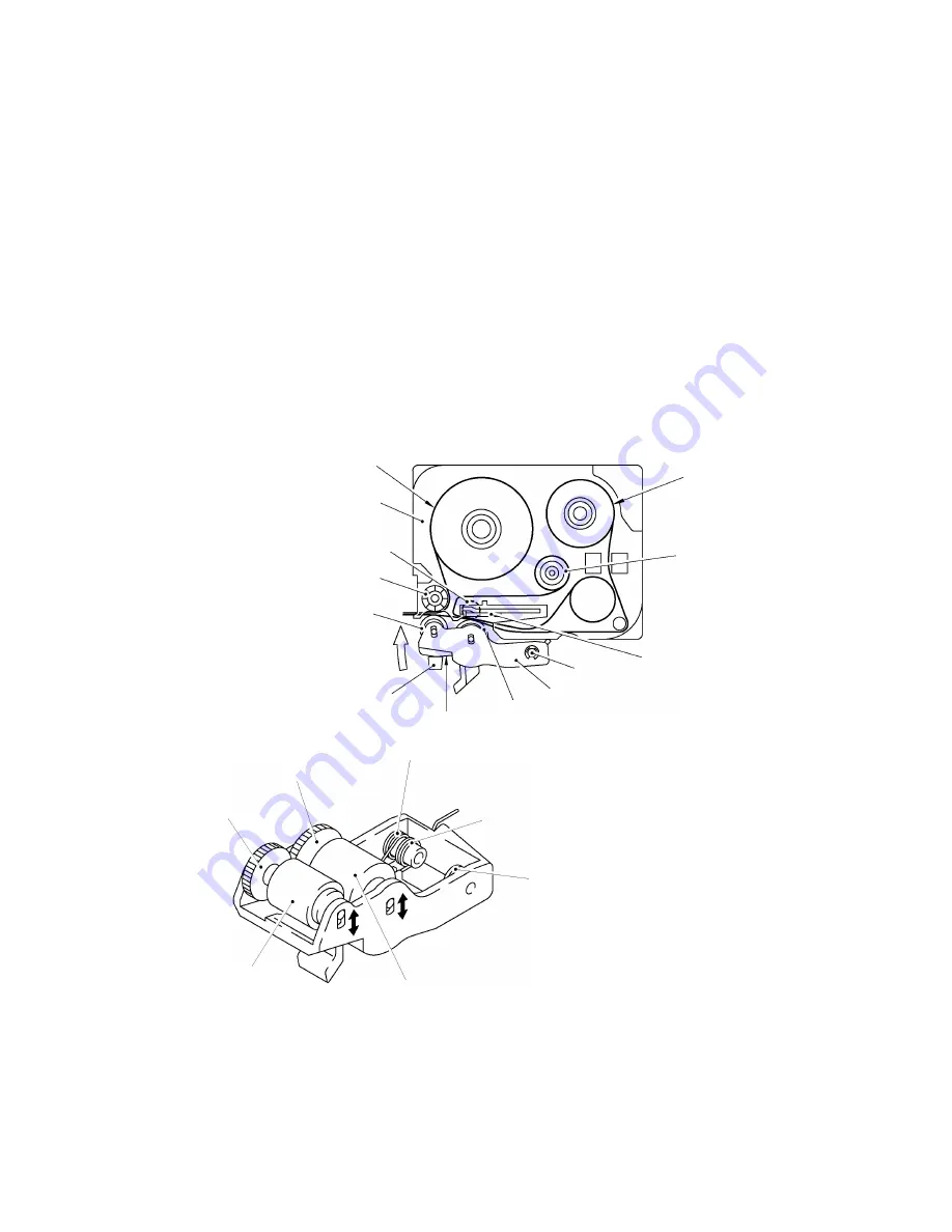
Platen Roller, (Tape Feed) Sub Roller Setting & Retracting Mechanism
This mechanism consists of the holder cam (cassette cover ASSY) and the roller holder ASSY.
The roller holder ASSY supports the platen roller and the sub roller so that :
Ÿ
the platen roller can move perpendicularly to the thermal head and rotate freely and
Ÿ
the sub roller can move perpendicularly to the tape feed roller and rotate freely.
By closing the cassette cover ASSY, the holder cam of cassette cover ASSY pushes the roller
holder ASSY toward thermal head side by pushing A face of the roller holder ASSY.
The platen roller is pressed perpendicularly against the thermal head with the tape and ink ribbon
(only the tape when using non-laminated thermal film tape cassettes) sandwiched inbetween under
a uniform load by the roller holder springs (upper and lower). Also, the (tape feed) sub roller is
pressed perpendicularly against the tape feed roller built in the tape cassette with the tape (the
laminate tape and adhesive base tape when using laminated tape cassettes) sandwiched
inbetween by the roller holder springs (upper and lower) and at the same time the (tape feed) sub
roller gear becomes engaged with the tape idle gear.
Opening the cassette cover ASSY, (the holder cam of the cassette cover ASSY is released from
the roller holder ASSY), retracts the roller holder ASSY from the thermal head, providing you with
enough space to replace the tape cassette.
Fig. 2.1-2 Platen and (Tape Feed) Sub Roller Setting & Retracting Mechanism
Laminate tape
Roller holder ASSY
Shaft
Platen idle gear
Holder cam
A
Platen roller
Adhesive base tape
Thermal head
Ink ribbon
(Tape feed) sub roller
Tape feed roller
Tape cassette
Roller holder lower spring
(Tape feed) platen gear
(Top)
(Tape feed) sub roller gear
Roller holder release spring
Platen roller
Roller holder upper spring
(Tape feed) sub roller
Содержание P-touch PT-1100
Страница 2: ...SERVICE MANUAL MODEL PT 1100 1130 1170 1180 11Q PT 1250 1160 ST 1150 Heavy Duty LabelerTM ...
Страница 5: ...CHAPTER I SPECIFICATIONS ...
Страница 9: ...I 3 Fig 1 1 2 Key Arrangement 1 ...
Страница 10: ...I 4 Fig 1 1 2 Key Arrangement 2 ...
Страница 11: ...I 5 Fig 1 1 2 Key Arrangement 3 ...
Страница 13: ...CHAPTER II MECHANISMS ...
Страница 50: ...35 II 2 3 4 Troubleshooting Flows 1 Tape feeding failure ...
Страница 51: ...36 II ...
Страница 52: ...37 II 2 Printing failure ...
Страница 53: ...38 II ...
Страница 54: ...39 II 3 Powering failure Nothing appears on the LCD ...
Страница 55: ...40 II 4 No key entry possible ...
Страница 56: ...CHAPTER III ELECTRONICS ...
Страница 75: ...III 17 3 3 3 Troubleshooting Flows 1 Tape feeding failure 2 Printing failure ...
Страница 76: ...III 18 3 Powering failure Nothing appears on the LCD ...
Страница 77: ...III 19 4 Abnormal LCD indication ...
Страница 78: ...III 20 5 No key entry possible 6 Tape cassette type not identified ...
Страница 80: ......
Страница 81: ......
Страница 82: ......
Страница 83: ...Jan 2002 8V2010BE1 Printed in Japan ...


