KE-434C,435C
CONTENTS
1. NAME OF EACH PART ..............................
1
2. SPECIFICATIONS ......................................
2
2-1. Specifications......................................................... 2
2-2. Examples of sewing patterns ................................. 3
3. INSTALLATION ..........................................
4
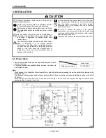
3-1. Power table............................................................ 4
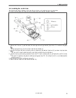
3-2. Installing the control box ........................................ 5
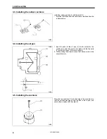
3-3. Installing the rubber cushions ................................ 6
3-4. Installing the oil pan ............................................... 6
3-5. Installing the cushions............................................ 6
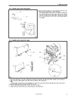
3-6. Installing the switching plate .................................. 7
3-7. Installing the machine head ................................... 7
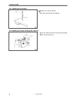
3-8. Installing the head rest........................................... 8
3-9. Installing the liquid cooling tank, optional ............... 8
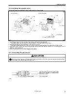
3-10. Installing the operation panel ............................... 9
3-11. Connecting the ground wire ................................. 9
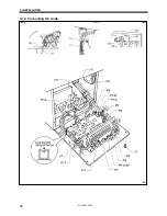
3-12. Connecting the cords .......................................... 10
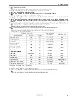
3-13. Piping (for pneumatic)......................................... 13
3-14. Installing the belt cover ....................................... 16
3-15. Installing the foot switch...................................... 16
3-16. Installing the needle sub plate ............................ 17
3-17. Installing the spool stand .................................... 18
3-18. Installing the eye guard....................................... 18
4. LUBRICATION...........................................
19
4-1. Lubrication points.................................................. 19
5. OPERATION ..............................................
20
5-1. Name and function of each operation panel item ..... 20
5-2. Operating procedure ............................................. 22
5-3. Operating the foot switch ...................................... 24
5-4. Operating the emergency stop switch ................... 25
5-5. Operating the thread wiper switch (KE-435C)....... 25
6. CHECKING THE SEWING PATTERN........
26
7. CORRECT USE .........................................
27
7-1. Selecting the needle and thread ........................... 27
7-2. Installing the needle .............................................. 27
7-3. Threading the upper thread .................................. 27
7-4. Winding the lower thread ...................................... 28
7-5. Replacing the bobbin case and
threading the thread.............................................. 29
7-6. Thread tension...................................................... 29
8. SEWING ....................................................
32
9. MAINTENANCE AND INSPECTION..........
33
9-1. Checking the needle ............................................. 33
9-2. Cleaning the rotary hook....................................... 33
9-3. Lubrication ............................................................ 34
9-4. Draining the oil...................................................... 35
9-5. Cleaning the control box air inlet port.................... 35
9-6. Cleaning the air holes of belt cover
and frame side cover ............................................ 35
9-7. Cleaning the eye guard......................................... 35
10.
STANDARD ADJUSTMENTS...................
36
10-1. Adjusting the needle bar height ...........................36
10-2. Adjusting the needle bar lift amount ....................36
10-3. Adjusting the driver needle guard ........................37
10-4. Adjusting the needle clearance ...........................37
10-5. Adjusting the shuttle race thread guide ...............37
10-6. Adjusting the thread take-up amount...................38
10-7. Adjusting the movable knife.................................39
10-8. Adjusting the work clamp lift amount ...................42
10-9. Work clamp interchangeability.............................43
10-10. Adjusting the needle up stop position ................43
10-11. Adjusting the thread wiper .................................44
10-12. Checking the input sensor and DIP switch input ..... 45
10-13. Checking the input voltage ................................46
10-14. Clearing all memory settings .............................46
10-15. Moving stitch patterns .......................................47
10-16. Adjustment of air pressure (for pneumatic)........48
10-17. Adjustment of inner clamping device .................48
10-18. Work clamp adjustment (KE-435C) ...................49
10-19. Changing the work clamp lift (KE-435C)............49
11. USING THE COUNTERS .........................
50
11-1. Using the bobbin thread counter .........................50
11-2. Using the production counter...............................50
12. CHANGING FUNCTIONS USING
THE DIP SWITCHES................................
51
12-1. Operation panel DIP switches .............................51
12-2. DIP switches inside the control box .....................52
12-3. Using user programs ...........................................53
13. CHANGING SPECIAL FUNCTIONS
USING THE MEMORY SWITCHES
.........
55
13-1. Using the cycle sewing function ..........................58
14. SETTING THE WORK CLAMP MODE.....
60
14-1. Setting solenoid work clamp mode ......................60
14-2. Setting pneumatic work clamp mode...................60
14-3. Light work clamp .................................................62
14-4. Setting reverse work clamp mode .......................63
15. TABLE OF ERROR CODES ....................
64
16. GAUGE PARTS LIST ACCORDING TO
SUBCLASSES .........................................
66
17.
MAKING THE FEED PLATE AND WORK CLAMP
PLATE FOR INNER CLAMPING DEVICE
.........
69
17-1. Sewing area ........................................................69
17-2. How to make a sewing pattern ............................69
17-3. How to make the feed plate.................................70
17-4. How to make the work clamp plate......................71
17-5. Replacing the work clamp crank and work clamp
plate holder..........................................................72
18. TROUBLESHOOTING .............................
73
19. OPTIONAL PARTS ..................................
76


