IV –
16
(5)
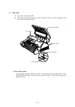
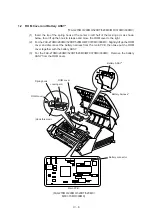
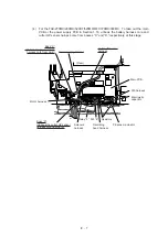
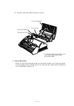
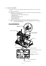
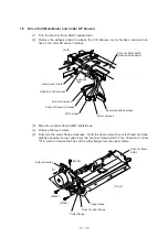
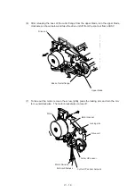
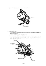
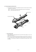
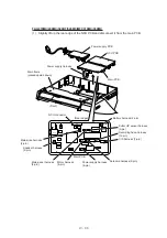
Lift up the ACS grounding spring.
■
Reassembling Notes
•
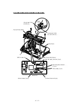
Before putting the scanner frame ASSY back onto the main frame, be sure to set the ACS
grounding spring as illustrated on the previous page.
•
Make sure that tabs “A” of the scanner frame ASSY are fitted in cutouts “B” provided in
the main frame. (See the illustration on the previous page.)
•
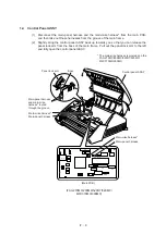
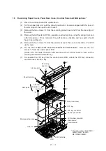
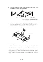
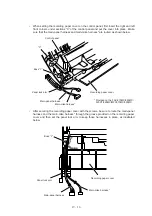
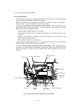
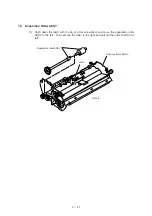
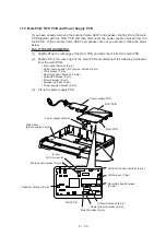
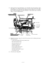
For the FAX-270MC/290MC/520DT/520MC/MFC370MC/390MC: After putting the scanner
frame ASSY back onto the main frame, route the harnesses and arrange the cores as
follows, referring to the illustration below.
-
Hook the power supply harness core on boss “C.”
-
Check that the cutter HP sensor harness runs through a core, and then hook the core
on boss “D.”
-
Push the CIS harness core and the recording head harness core into position, to the
left of rib “E” and behind relay “F.”
-
Route all these harnesses under boss “D.”
If any of these harnesses and cores are out of the specified position, the scanner frame
ASSY or ROM cover may not be put back into place.
•
For the FAX-270MC/290MC/520DT/520MC/MFC370MC/390MC: After connecting these
harnesses, check that neither the electrolytic capacitor nor resistors are tilted towards the
PE sensor actuator. If tilted, they may interfere with normal operation of the sensor
actuator.
Electrolytic
capacitor
Cutter HP sensor
harness
(Rear)
Boss “C”
Power supply harness
Main PCB
CIS harness
PE sensor actuator
Resistors
Recording
head harness
Rib “E”
Relay “F”
Solenoid
harness
Boss “D”
Motor harness
(FAX-270MC/290MC/520DT/520MC/MFC370MC/390MC)
Содержание FAX-270MC
Страница 4: ...CHAPTER I GENERAL DESCRIPTION ...
Страница 11: ...CHAPTER II INSTALLATION ...
Страница 12: ...CHAPTER III THEORY OF OPERATION ...
Страница 49: ...CHAPTER IV DISASSEMBLY REASSEMBLY AND LUBRICATION ...
Страница 86: ...IV 36 4 Cutter unit Cutter unit A A A A ...
Страница 87: ...CHAPTER V MAINTENANCE MODE ...
Страница 140: ...CHAPTER VI ERROR INDICATION AND TROUBLESHOOTING ...
Страница 157: ...March 98 5X1S112 Printed in Japan ...
Страница 173: ...D POWER SUPPLY 100 120 V U S A CANADA ...
Страница 174: ...POWER SUPPLY 200 240 V EUROPE SOUTH AMERICA D ...
Страница 175: ...POWER SUPPLY 200 240 V GULF ASIA CHINA D ...
Страница 192: ...D POWER SUPPLY 100 120 V U S A CANADA ...
Страница 193: ...POWER SUPPLY 200 240 V EUROPE SOUTH AMERICA D ...
Страница 194: ...POWER SUPPLY 200 240 V GULF ASIA CHINA D ...
Страница 195: ...FACSIMILE EQUIPMENT PARTS REFERENCE LIST MODEL FAX170 190 190 Plus 195 ...
Страница 198: ......
Страница 203: ......
Страница 206: ...Remarks 8 8 8 8 8 8 9 9 8 8 8 8 8 8 0 1 0 1 Brother Technical Information FAX98250 4 ...
Страница 208: ... 8 01 8 01 8 8 8 8 0 1 0 1 8 8 8 8 Brother Technical Information FAX99102 6 ...
Страница 220: ......

