V –
30
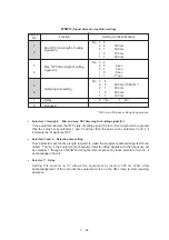
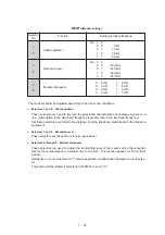
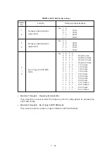
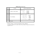
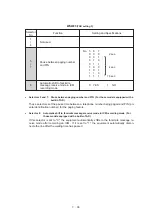
WSW18
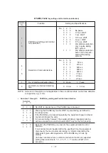
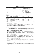
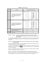
(Function setting 3)
Function
Selector
No.
Setting and Specifications
1
CCD manufacturer setting
Fixed to 1.
2
3
4
0:
Operative
1:
Inoperative
ACS* check sheet output
function on/off key
5
0:
ON
1:
OFF
ACS* check sheet output
function
6
Registration of station ID
0:
Permitted
1:
Prohibited
7
8
Tone sound monitoring
No. 7
8
0
X
:
No monitoring
1
0
:
Up to phase B at the
calling station only
1
1
:
All transmission phases
both at the calling and
called stations
No. 2
3
0
0
:
40 sec.
0
1
:
0 sec. (No detection)
1
0
:
5 sec.
1
1
:
80 sec.
* ACS: Anti-curl system
●
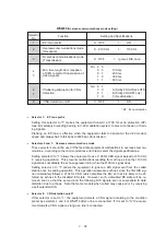
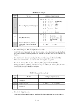
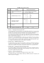
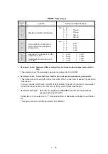
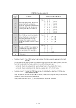
Selector 1:
CCD manufacturer setting
Reserved for future variation of CCD.
●
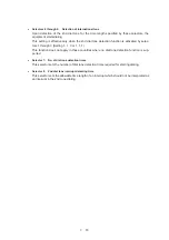
Selectors 2 and 3: Detection enabled time for CNG and no tone
After the line is connected via the external telephone, the equipment can detect a CNG sig-
nal or no tone for the time length specified by these selectors. The setting specified by these
selectors becomes effective only when selector 8 of WSW20 is set to "1."
●
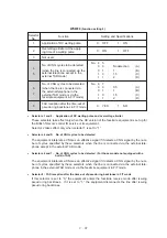
Selector 4: ACS check sheet output function on/off key
If this selector is set to "0" (Operative), the user can toggle the ACS check sheet output func-
tion on and off by pressing the 1 and 5 keys simultaneously. If it is set to "1" (Inopera-
tive), the user cannot toggle the ACS check sheet output function from the control panel so
that the setting specified by selector 5 becomes effective.
●
Selector 5: ACS check sheet output function
When selector 4 is set to "0," the setting specified by this selector becomes the default state
of the ACS check sheet output function. When selector 4 is set to "1," the setting specified
by this selector becomes permanently effective.
●
Selector 6:
Registration of station ID
Setting this selector to "0" permits the registration of station ID for Austrian and Czecho ver-
sions.
●
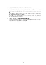
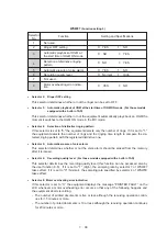
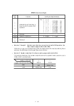
Selectors 7 and 8: Tone sound monitoring
These selectors sets monitoring specifications of the tone sound inputted from the line.
Detection enabled time for CNG
and no tone
Содержание FAX-270MC
Страница 4: ...CHAPTER I GENERAL DESCRIPTION ...
Страница 11: ...CHAPTER II INSTALLATION ...
Страница 12: ...CHAPTER III THEORY OF OPERATION ...
Страница 49: ...CHAPTER IV DISASSEMBLY REASSEMBLY AND LUBRICATION ...
Страница 86: ...IV 36 4 Cutter unit Cutter unit A A A A ...
Страница 87: ...CHAPTER V MAINTENANCE MODE ...
Страница 140: ...CHAPTER VI ERROR INDICATION AND TROUBLESHOOTING ...
Страница 157: ...March 98 5X1S112 Printed in Japan ...
Страница 173: ...D POWER SUPPLY 100 120 V U S A CANADA ...
Страница 174: ...POWER SUPPLY 200 240 V EUROPE SOUTH AMERICA D ...
Страница 175: ...POWER SUPPLY 200 240 V GULF ASIA CHINA D ...
Страница 192: ...D POWER SUPPLY 100 120 V U S A CANADA ...
Страница 193: ...POWER SUPPLY 200 240 V EUROPE SOUTH AMERICA D ...
Страница 194: ...POWER SUPPLY 200 240 V GULF ASIA CHINA D ...
Страница 195: ...FACSIMILE EQUIPMENT PARTS REFERENCE LIST MODEL FAX170 190 190 Plus 195 ...
Страница 198: ......
Страница 203: ......
Страница 206: ...Remarks 8 8 8 8 8 8 9 9 8 8 8 8 8 8 0 1 0 1 Brother Technical Information FAX98250 4 ...
Страница 208: ... 8 01 8 01 8 8 8 8 0 1 0 1 8 8 8 8 Brother Technical Information FAX99102 6 ...
Страница 220: ......

