background image

Chapter 5   Adjustment

For raising the head, refer to “3. How to
raise the head” in “Chapter 4. Oiling”.

Содержание BAS-6150

Страница 1: ...INSTRUCTION MANUAL BAS 6150 AUTOMATIC LOCKSTITCH POCKET WELT SEWER Please read this manual before using the machine Please keep this manual within easy reach for quick reference ...

Страница 2: ......

Страница 3: ...and to prevent hazards from an operator and or other people The meanings of these indications and symbols are given below SAFETY INSTRUCTIONS Indications The instructions following this term indicate situations where negligence of the instructions will almost certainly result in death or severe injury The instructions following this term indicate situations where negligence of the instructions to ...

Страница 4: ... Installation Use the machine in an area free of the impact from sources of strong electrical noise such as high frequency welders Sources of strong electrical noise may cause problems with correct operation of the machine Any fluctuations in the power supply voltage should be within 10 of the rated voltage for the machine Voltage fluctuations greater than this range may cause problems with correc...

Страница 5: ...rect operation and abnormal sound or smell are noticed Contact your Brother dealer or a qualified technician Contact your Brother dealer or a qualified technician when the machine is in trouble Sewing The machine should be operated only by operators who have been trained for safety operation Do not let children access to the machine The machine should not be used for any other application than sew...

Страница 6: ...se injury maintenance adjustment and repairment replacement of consumable parts such as the rotary hook knife lamp etc When adjustment has to be done with the power switch and air supply on pay enough attention to safety Detach the air tube of air source and set the pointer of the pressure gauge to 0 for inspection adjustment and repair of air using devices Maintenance and inspection Turn off the ...

Страница 7: ...f main switch before changing needle cleaning etc Hazardous voltage will cause injury Turn off main switch and wait 5 minutes before opening this cover Un voltage non adapt provoque des blessures Eteindrel interrupteur et attendre 5 minutes avantd ouvrir le capot Hochspannung verletzungsgefahr Bitte schalten sie den hauptschalter aus und warten sie 5 minuten bevor sie diese abdeckung ffnen Un volt...

Страница 8: ... 20 4 3 How to wind the lower thread 21 4 4 How to thread the lower thread 22 4 5 How to thread the upper thread 23 4 6 Adjusting the thread tension 23 4 7 Retention of upper and lower threads 24 4 8 Adjusting the thread tension spring 25 4 9 Initialization at the time of power ON 26 Chapter 2 Sewing flow 27 1 Outline of operation 28 1 1 Description of the panel 28 1 2 How to operate the 3 pedal s...

Страница 9: ...ustment of carriage feed 60 6 Explanation of sensor amplifier 61 7 Adjustment of flap sensor flap specifications 62 7 1 Before starting flap sewing 62 7 2 How to set the detection sensitivity 63 8 Adjustment of the lower thread detection sensor option 65 8 1 How to wind the lower thread 65 8 2 How to set the detection sensitivity 66 9 Adjustment of the upper thread breakage sensor option 67 Chapte...

Страница 10: ... 5 Sensor check 89 5 1 Sensor switch 90 5 2 DIP switch 91 5 3 Voltage of 210 V and 55 V 91 5 4 Voltage of 30 V and 24 V 91 6 ROM version display 92 Chapter 8 Dipswitch 93 DIP SW A Control panel 94 DIP SW B Main print circuit board 94 DIP SW C Main print circuit board 95 Chapter 9 Error code List 97 Error code List 98 Chapter 10 Troubleshooting 101 Reference table in trouble 102 ...

Страница 11: ...Chapter 1 Machine Preparation ...

Страница 12: ...e OFF Maximum 220mm standard 250mm option Program number 10 enable to copy Cycle program number 5 4 prgrams 1 cycle stacker movable in the middle Lower thread counter 0 999 disable when remaining amount detection device in use Sensor check function Display of conditions of sensors switches etc Needle gauge 8 10 12 14 16 18 20 mm Standard 12mm Needle to be used Mtx190 16 14 18 Rotary hook Horizonta...

Страница 13: ...BAS 6150 11 2 Name of parts 1435S Cotton stand Control panel Emergency stop switch Power switch Caster 3 pedal switch Table L Guard bar option Stacker option Cover Marking light Marking light Binder Flap clamp Carriage feed Table R ...

Страница 14: ...ble 3 2 How to install the machine 1 Loosen nut q and adjust the height of caster w so that the power table be parallel with the surface of the floor 2 Descend lever e in order not to move the main body and fix caster w Up lever e then the main body can be movable Note If the floor is not solid enough the machine may become unstable Lay something solid like concrete plates and precede the installa...

Страница 15: ...0 13 3 3 Installation of the 3 pedal foot switch Plug connector w of 3 pedal foot switch q into the connector on the front side 3 4 Attachment of the cotton stand Put cotton stand q into bracket w and fix with screw e q w w e q 1438S 1439S ...

Страница 16: ...t the top of the leg Fix them with four bolts e respectively e w q 3 5 Detachment of the emergency stop switch cover Unscrew two tightening screws q and detach emergency stop switch cover w Attach the emergency stop switch cover to protect the emer gency stop switch Keep the emergency stop switch cover with good care OFF O N OFF O N w q 1440S 1441S ...

Страница 17: ... guard t to guard base y with bolts r at right and left ends 3 Attach chain o to stacker i and guard t with bolt u y r t r i t u o u o 1442S 4 Connect air hose 1 from manifold 0 on the stacker to plumber module 3 of regulator 2 1 0 3 2 1 4 1443S 1444S ...

Страница 18: ...Chapter 1 Machine Preparation BAS 6150 16 5 Connect bar stacker harness 4 to P20 on main circuit board 5 in the control box 4 5 1445S ...

Страница 19: ... the pointer of the pressure gauge to 0 for inspection adjustment and repair of devices using air 1 Joint rubber hose q to union e of air unit w 2 Turn handle r while pulling up it to set air pressure to 0 49 Mpa 3 When water is noticed in bottle t drain water by pressing the button of the drain cock y Note When bulb u is opened pay due attention to movement of the stacker bar q w e r u t y CAUTIO...

Страница 20: ...he main plate Pull up plunger q and lock it and then open main plate w Note Open or close main plate w with binder e held up by hand not to touch the needle when the binder e is in down position Binder e goes down when the power or air supply is OFF 1448S q w e ...

Страница 21: ...aration for sewing 4 1 How to mount the needle 1 Rotate the pulley to lift the needle to the highest point 2 Pull up the plunger and lock it and then open the main plate Refer to 3 8 How to open the main plate 3 Loosen set screw q 4 Thrust needles w up straight with their long grooves facing to the inside and fasten up set screw q CAUTION 1449S q w w Long groove ...

Страница 22: ...ulley to lift needle q to the highest point 2 Open the slide plate 3 Dismount bobbin case e and bobbin r after pulling up rotary hook hold w Proceed to following steps at the occurrence of the lower thread breakage after an error is reset by pressing the reset switch After finishing with the steps proceed to the next steps in accordance with 4 3 How to wind the lower thread and 4 4 How to thread t...

Страница 23: ... over lever e returns to original position and thread roll axis w stops 6 Loosen set screw r and move lever e to right and left for adjustment of thread winding amount of bobbin q 7 Detach bobbin q from shaft w Cut the thread while winding the middle part of thread onto thread nipper t At the next winding of the thread pick up the end of the thread from thread nipper t and roll it onto bobbin q No...

Страница 24: ...hed Otherwise unintended press on the foot switch may cause injury 1 Cover bobbin w with bobbin case q 2 Let the thread through slit e and go through under timing spring r 3 Pull out the thread by approx 50 mm from the thread hole at the end of spring r 4 Put bobbin case q and bobbin w into the rotary hook 50mm r q e w CAUTION 1455S ...

Страница 25: ...the following steps at the occurrence of upper thread breakage after the error is reset by pressing the reset switch 1 Lift up the plunger and lock it and then open the main plate 2 Rotate the pulley to set the thread take up q at the highest position and start threading from the tread take up on the left Threading at the highest position is for easy threading and good prevention of the thread com...

Страница 26: ...read trimmer knife 7 Press the FEED key q to move the carriage feed to the standby position When the setting for the memory switch 3 environment parameter No 63 is set to ON press the ENTER key r with the FEED key q being pressed 2 Open the slide plate 3 Cover the bobbin with the bobbin case Place them into the rotary hook leaving the end of the thread t out about 50 mm and pull down the nipper Pu...

Страница 27: ...n turn the thread tension stud u to adjust the tension 4 Tighten the screw t and then tighten the knob y Thread take up spring R w 1 Loosen the set screw i 2 Loosen the knob y and then turn the adjustment knob o to adjust the tension 3 Tighten the screw i and then tighten the knob y 4 8 3 Thread take up spring operation timing The standard operation timing for thread take up spring L q and thread ...

Страница 28: ... holding down RESET key q and ENTER key w turn on the power switch The start switch is not pressed Hold the DIP switch B 7 and B 8 to be ON to initialize the Environment parameter Refer to Chapter 8 Dip switch 2 The gauge needle gauge setting screen appears Select the gauge size needle gauge by pressing key 3 Initialization is performed as for the memory by pressing ENTER key w 4 9 2 Initializatio...

Страница 29: ...Chapter 2 Sewing flow ...

Страница 30: ...placed at the feed position LED blinks When the setting for the memory switch 3 environment parameter No 63 is set to ON press the ENTER key y with the FEED key w being pressed e NDL THREAD CUT upper thread cut The upper knife comes out only while the key is pressed and trims the upper thread as it retracts when the key is released when the carriage feed is at the feed position r BBN THREAD CUT lo...

Страница 31: ...ow Contents of the program or those of the parameter are displayed 2 Display of knife setting CUTTER The lamp turns on when the center knife operation setting is ON CORNER CUT The lamps turns on when the corner knife operation setting is ON 3 Setting menu The menu to be displayed can be changed by pressing the SELECT key t Displays in the display window and key functions when each menu is selected...

Страница 32: ...indow 0 u Program No Program No change Contents display window 1 i o Correction value Setting for the center and corner knives Program No display window 0 u Program No Program No change ADJUST Display of center and corner knives correction value Startofsewingcenterknifecorrection End of sewing center knife correction Start of sewing corner knife correction End of sewing corner knife correction Whe...

Страница 33: ...ction counter is displayed top 2 digits are displayed out of total 6 digits of the production counter Lower thread volume sensor in use The production counter is displayed while the RESET key is pressed When the production counter is displayed bottom 4 digits are displayed out of total 6 digits of the production counter When the cycle program is selected the progress is changed within the cycle pr...

Страница 34: ...o down Setting is needed 3rd The folding plate comes out after the binder goes down Setting is needed 4th Either left or right one of flap clamps goes down Setting is needed 5th Either left or right one of flap clamps goes down Setting is needed 3 Functionofthe foot backwardswitch Revert one step of the previous clamping action at each press down Binder Flap clamp R Carriage feed R Folding plates ...

Страница 35: ...s down the start switch w The home position is automatically set Note When the setting for the memory switch 1 en vironment parameter No 61 is set to ON and the home position is to be set the center knife moves up and down Be careful in order not to be injured and not to put cloth and the like around the knife 3 Press key to select the sewing program w 1462S 1463S ...

Страница 36: ...y w TEST is displayed in the contents display window r and the mode becomes the test operation mode 4 Continuous operation starts by continuous press of the start switch e 5 One step operation is performed by pressing the forward switch q 6 Continuous operation is performed by continuous press of the forward switchq 7 One step backward is performed by pressing the backward switch t 8 Continuous ba...

Страница 37: ...down 4 Press down forward switch q once more and carriage feed left e goes down 5 Set the cloth to be welted 6 Press down forward switch q once more and binder r goes down and the folding plate operates After binder r goes down to hold the cloth to be welted the folding plate operates to fold the cloth to be welted 7 Press down the start switch and sewing is started Press the emergency stop switch...

Страница 38: ... if the start switch is press unless the flap clamp goes down on the flap program mode 1 Operate in accordance with steps 1 through 6 Standard sewing 2 Set the left flap 3 Press down the forward switch five times and flap clamp left w goes down The cloth can be set with steps above completed 1470S ...

Страница 39: ...ing light turns on when the power switch q is set to ON 2 Loosen screw w and adjust the focus by letting lens hood e up and down to be able tohaveaclearviewofthemark reflected onthecloth 3 Set the mark at the best position for startup and end of sewing by loosening fly screw r Note Findthefrontandrearpositionofsewingstartup by adjusting bolt t 1462S 1471S t r w ...

Страница 40: ...en the RESET key w is pressed If the emergency stop switch is pressed in sewing press the start switch furthermore The feeder moves to the feed position 1472S Machine operation can be stopped by pressing the emergency stop button The emergency stop button is of push turn lock type 1457S 3 3 Post process after the machine stop due to errors If an error is displayed when the power supply is on or in...

Страница 41: ...Chapter 3 Settings ...

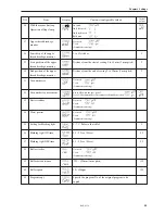
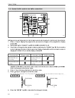
Страница 42: ...ode by pressing the ENTER key e The parameter No is lit on the program No display window r The contents of the parameter is lit to blink in the contents display window y Display and contents are displayed alternately 4 Press key to change the parameter No in the program No display window r 5 Press key to change the contents Return to step 4 if you need to change other parameters 6 Press the ENTER ...

Страница 43: ... 2500 2 4 4 0 1000 1 0 1 Initial values Seam length Flap sewing Flap correction start of sewing Flap correction end of sewing Flap clamp Flap clamp operation Sewing speed at lock stitch sewing Stitch pitch Tack stitch method start of sewing and end of sewing in common Tack stitch length start of sewing and end of sewing in common Sewing speed at tack stitch start of sewing and end of sewing in com...

Страница 44: ...of clamping Clamp movement speed sewing start position Clamp movement speed corner knife position Setting position of clamp movement Pick up operation mode Carriage feed movement at pick up return Application of pressure after T gauge goes down Settings for folding plate Folding plate movement at corner knife up Not used Used Automatic sensing Right to left Left to right Concurrent movement of rig...

Страница 45: ...th the foot pedal Set to ON automatically at the carriage feed standby position Not used Used Automatic sensing Not used Used Automatic sensing Not used Used Automatic sensing With the corner knife up Operation of flap clamp Upper thread breakage monitor Sensitivity of the upper thread breakage monitor Start position of the upper thread breakage monitor End position of the upper thread breakage mo...

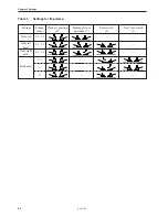
Страница 46: ... 6150 Settings Setting Cloth set position Folding plate in Foot switch Next foot switch values 0 operation 1 2 3 Table 1 Settings for flap clamp Not used 0 1 2 3 0 1 2 3 0 1 2 3 0 3 1 2 Only left used Only right used Both used ...

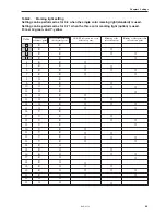
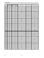
Страница 47: ...R G 32 G G 33 G G Table2 Marking light setting Setting can be performed as for 0 3 when the single color marking light standard is used Setting can be performed as for 0 71 when the three color marking light option is used R red G green and Y yellow Color at the reference point ON OFF selection for every reference point Blinking at the reference point Blinking at other points than the reference po...

Страница 48: ...0 R Y 51 R Y 52 R Y 53 R Y 54 R Y 55 R Y 56 G Y 57 G Y 58 G Y 59 G Y 60 G Y 61 G Y 62 G Y 63 G Y 64 Y Y 65 Y Y 66 Y Y 67 Y Y 68 Y Y 69 Y Y 70 Y Y 71 Y Y Color at the reference point ON OFF selection for every reference point Blinking at the reference point Blinking at other points than the reference point Color at other point than the reference point ...

Страница 49: ...tion flap front end stop at the needle down position 3 Adjust the front and rear position of the feeder with key 4 The value is memorized and the parameter No 3 Flap correction End of sewing is displayed The operation proceeds as described below feeder forward further flap rear end detection flap rear end stop at the needle down position 5 Adjust the front and rear position of the feeder with key ...

Страница 50: ...nife and corner knife correction 1457S Correction value Display symbol Correction value Display symbol LED y in CUTTER in correction of the center knife blinks and so does LED u in CORNER CUT in correction of the corner knife 4 Press key to change the kind of correction value 5 Press key to change the correction value The correction value ranges from 9 9 to 9 9 in the unit of 0 1 mm Nos do not sho...

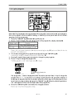
Страница 51: ...te in the program No display window q 4 Press to select the program you want to change in cycle programs 5 Press key to change the program No The blinking program No on the contents display window t is changed 1481S 1482S The dot denotes the stacker is to operate The program No which is displayed to blink has been selected Press key to change the program No is used when no setting is performed for...

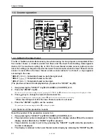
Страница 52: ...TER key t The mode is set to the counter setting mode by pressing the ENTER key t and the previous setting value is displayed to blink 3 Press key to change the lower thread counter No A number is blinking in the contents display window r while the lower thread counter is in setting When the setting set at 000 the lower thread counter is not used 4 Press the ENTER key t to set the number The numbe...

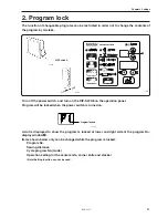
Страница 53: ...le program No mode Operation setting for the center knife corner knife and stacker Note Setting function can not be used 2 Program lock The function of changeable programs can be restricted in order not to change the contents of the program by mistake 1457S Turn off the power switch and turn on the DIP SW A8 on the operation panel Program will be locked when the power switch is turned on 1483S Pro...

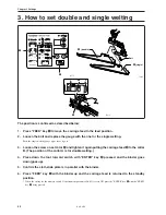
Страница 54: ...screw on set color r and tighten it again putting the carriage feed e to the collar B The position of the collar A is for double welting 4 Press down the foot forward switch with ENTER key w pressed and the binder goes down goes up 5 Confirm the cloth slide plate is in parallel with the binder 6 Press FEED key q with the binder up and the carriage feed is returned to the standby position When the ...

Страница 55: ...Chapter 4 Oiling ...

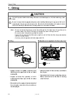
Страница 56: ... so on Be sure to conduct oiling before operating the machine Supply oil to the extent that the felt absorbs oil lightly Lack of oil in the felt of the rotary hook assembly may cause sewing troubles Use the machine oil specified by Brother high white 70 Supply oil from oil cap q so that the oil is filled up to the upper part of the oil meter window w Supply oil when the quantity of oil is reduced ...

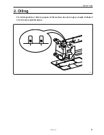
Страница 57: ...Chapter 4 Oiling BAS 6150 55 2 Oiling For initial operation or after long repose of the machine be sure to apply a couple of drops of oil to the arrow pointed places 1487S ...

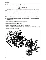
Страница 58: ...tention to safety when adjusting is needed with the power switch and air supply ON Maintenance and inspection of the machine should be performed only by technicians who have been properly trained 3 How to raise the head 1 Lift up cloth slide plate q and turn it to be perpendicular 2 Dismount pivot pin w from the sub table 3 Pull and lock shaft stopper e located at the rear and lower end 4 Dismount...

Страница 59: ...Chapter 5 Adjustment For raising the head refer to 3 How to raisethehead in Chapter4 Oiling ...

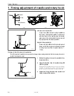
Страница 60: ...e 1 1 5mm q Needle 1 1 5mm 2 4mm Standard w e 1492S 1491S 1490S 1588S 1589S 2 4 2 8 3 5 2 4 2 8 3 5 2 4 2 8 3 5 2 4 2 8 3 5 r Gauge Gauge Change of the lift amount of needle bar The lift amount of needle bar is required to change when sewing materials that are uneasy to make a needle hole loop are used 1 Rotate the pulley to move the needle to the lowest position 2 Align the bottom face of needle ...

Страница 61: ...ve q to left and right so that the clearance between the needle and rotary hook blade top be 0 05mm 3 Fasten screws A B and C tightly after adjustment Note Fasten set screw C at the position where lower shaft gear w touches lightly with guide plate e Fasten set screw C so as not to change the tightening force of set screw C lower shaft gear w Rotary hook blade top Needle No more than 0 05mm q w e ...

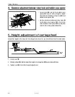
Страница 62: ...bout 20mm 3 Tighten nut q to lock after height adjustment q e w Approx 20mm Shaft 1497S Loosen bolt q and let the bobbin case opener w move to left and right to adjust the clearance between rotary hook e and bobbin case opener w Set the clearance between rotary hook e and bobbin case opener w to be 0 2mm when bobbin case opener w is pulled far most to the arrow pointed direction 0 2mm w q e 1496S ...

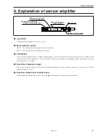
Страница 63: ...sor is displayed with numbers from 0 to 4090 when the mode selection switch is set to SET r Selection of detection output Which one of detection output 1 or 2 is selected is indicated Rotation of the jog switch can change 1 to 2 and vise versa For this equipment output 1 is used t Detection output action indicator lamp LED is turned on when the sensor is ON For this equipment the indicator 1 shows...

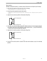
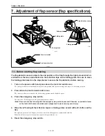
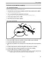
Страница 64: ...e The carriage feed moves forward to the cloth setting position and the flap hold opens 3 Press the emergency stop switch The error code E 500 appears on the panel and the buzzer sounds Note Be sure to conduct cleaning after the emergency stop switch is pressed Otherwise an accidental press on the foot switch causes the binder and carriage feed to move and may cause injury 4 Wipe the left and righ...

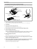
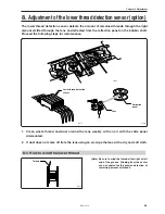
Страница 65: ...ll up lever w and mount cover q for the sensor amplifier Note Be sure to cut the top of fiber only by the dedicated fiber cutter which comes with at supply of the fiber Cutting by a nipper and other tools may cause low sensitivity and detection error Perform the following adjustment for left and right sensors 1 Dismount the cover for the sensor amplifier and set the mode selection switch to SET Co...

Страница 66: ...is pressed Otherwise an accidental press on the foot switch causes the binder and carriage feed to move and may cause injury 6 Reset the emergency stop switch The buzzer stops When the emergency stop switch is reset the feeding motor becomes free and the carriage feed can be moved manually 7 Move the carriage feed manually so that the end of the folding plate gets to the red spot position of the r...

Страница 67: ...or maintenance B L B R F L F R Lower thread detection sensor Reflection panel Lens 1 Clean waste thread and dust around the lens weekly with an air with the slide panel dismounted 2 If dust does not come off from the lens using an air wipe the lens with a dry and soft cloth Thread Note Be sure to wind the thread either right or left end of the groove Winding from the center can not guarantee the p...

Страница 68: ...er 5 Adjustment BAS 6150 66 8 2 How to set the detection sensitivity 8 2 1 Threshold value setting Refer to 7 2 1 Threshold value setting 8 2 2 How to insert the fiber Refer to 7 2 2 How to insert the fiber ...

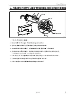
Страница 69: ... sensor w 4 Rotate volume e on the left clockwise until LED r on the left turns on 5 Rotate volume e on the left counter clockwise until LED r on the left turns off The adjustment of the sensor on the left is completed with steps above 6 The sensor on the right is adjusted with same steps as those of 4 and 5 above 7 Let the upper thread pass through between photo sensors 8 Close lid q for the uppe...

Страница 70: ...Chapter 5 Adjustment BAS 6150 68 ...

Страница 71: ...Chapter 6 Knife replacement ...

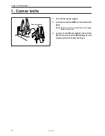
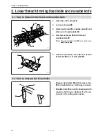
Страница 72: ... supply 2 Loosen the setscrew q to remove the knife base Note Be careful not to cut yourself on the finger with a corner knife 3 Loosen screw w and replace corner knife e Fix the corner knife e aligning its end surface with that of the knife base q w 1533S Align end surfaces e ...

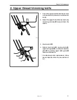
Страница 73: ...o be 0 2 Detach the upper thread trimmer device by loosening setscrew q and pull down the device 3 Unscrew bolt w 4 Detach fixed knife r moving knife t upper knife guide e and thread retention plate y by pulling upper knife guide e forward or backward For attachment after replacement follow above steps the other way around from 4 to 1 1512S q w e r t y 1513S ...

Страница 74: ...nscrew setscrew r and dismount movable knife t Note Dismount movable knife t so as not to dam age the top edge 5 Unscrew shoulder screw y and detach fixed knife u from needle plate w q w e t r t r y u u y w 3 2 How to sharpen the fixed knife u i 71 Sharpen fixed knife u with oil whet stone i as illustrated when cutting gets uneasy Movable knife t can not be sharpened with regular whet stones Repla...

Страница 75: ...ve connecting rod q go up Note Be careful of descent of upper knife w 3 Loosen flat head screw e and replace upper knife r with new one Note Press the upper knife to the deepest position for attachment 4 Rotate the upper shaft pulley and confirm the upper knife r goes up 5 mm high from needle plate t when the upper knife reaches to the highest point 1519S 1518S 1517S q w e r r t 5mm ...

Страница 76: ...e y from needle plate r For attachment after replacement follow above steps the other way around from 5 to 1 5 2 Position adjustment of the center knife upper knife and fixed knife 1 Replace the center knife with the center knife jig A accessory 2 Loosen the screw B and rotate the pulley to descend the center knife jig A 3 Rotate C and slide D Press the center knife jig A and the fixed knife toget...

Страница 77: ...Chapter 7 Environment setting ...

Страница 78: ...pressing the SELECT key w with the ENTER key q pressed Environment parameter Nos are displayed in the program No display window e to illuminate a dot at lower and right side distinguishes the environment parameter No from the parameter No Chapter 3 Setting and the contents of environment param eters is displayed in the contents display window r to blink Display and contents are displayed alternate...

Страница 79: ... sec 0 0 to 9 9 sec 15 to 45m min 5m min pitch 15 to 40m min 5m min pitch 15 to 40m min 5m min pitch 15 to 40m min 5m min pitch 9 9 to 9 9mm in the unit of 0 1 mm 0 1 2 3 4 5 6 7 8 9 10 11 12 12 0 2 0 2 0 3 0 0 30 30 30 30 0 0 NO Item Display Contents configurable values List of environment parameters Initial value Needle gauge Edge clearance of corner knives Corner knife position Standby timer af...

Страница 80: ...time after the last presser goes down 0 0 to 99 second s Setting is performed as for how many seconds later sewing is to start when the auto start is ON and when the start switch is pressed Setting is performed for operation interval by setting the display to ON and with operation of the foot switch 0 to 30 mm in the unit of 1 mm Distance from the start of sewing to the start of releasing the uppe...

Страница 81: ...pecified by symbols for the roller driving distance The roller stops with OFF ON ON edge The roller stops with ON OFF OFF edge These are conditions to top the roller when the roller cloth sensor is used 0 1 to 9 9 second s 0 1 to 9 9 second s Immediate stop 0 Stop at the end of sewing position 1 0 1 to 9 9 second Standby time for the start of the clamp s movement after the flap clamp ON 30 0 to 40...

Страница 82: ...tween the reference mark after clamping and the home position at the standby position 340 to 465 mm The distance between the reference mark after clamping and the needle drop position at the feed position 340 to 465 mm The distance between the reference mark after clamping and the home position at the stacking position 200 500 800 1000 1200 1500 1800 2000 2200 2500 2800 3000 rpm 35 0 0 30 340 465 ...

Страница 83: ...e misoperation is displayed when the FEED key is pressed is displayed when the ENTER key is pressed with the FEED key being pressed Carriage feed shift mode during operation with a stacker for preventing it from pinching cloth Carriage feed starts to shift after cloth is pressed Carriage feed starts to shift after cloth is discharged Binder up in detecting home position for preventing the carriage...

Страница 84: ...tial values for the stacker operation timer 0 0 0 5 0 4 0 6 0 0 0 0 6 0 5 0 3 0 5 0 5 0 7 1 0 0 0 5 0 3 0 8 0 5 1 0 Standard bar stacker option High feature bar stacker option Second Kind of corner knife edges Minimum sewing distance with the center knife OFF Minimum sewing distance with the center knife ON Edge clearance at the time of corner knife home position detection Clearance between the ne...

Страница 85: ...Chapter 7 Environment setting BAS 6150 83 Standard stacker 4 steps 0 1 3 4 2 1530S ...

Страница 86: ...Chapter 7 Environment setting BAS 6150 84 High feature stacker Mode 0 7 steps 0 3 4 1 5 6 7 2 1531S ...

Страница 87: ...Chapter 7 Environment setting BAS 6150 85 High feature stacker Mode 1 6 steps 0 3 1 4 5 6 2 1532S ...

Страница 88: ...top time in environment parameter setting 2 Likewise change the contents of environment parameter of No 57 Machine test mode to ON DISPLAY 3 With that condition press the start switch q and then the machine starts to operate The ENTER key e is not pressed 4 Press the RESET key w and then the machine stops to end the machine test mode 5 Press the ENTER key e to end the environment parameter setting...

Страница 89: ...the ON display 2 With that condition press the forward switch q and the mode is changed to the setting mode The ENTER key e is not pressed 3 Press the forward switch q to move the clamp in the specified order The interval of each operation is memorized Pressing the backward switch w returns one step of operation 4 Press forward switch q to descend all clamps 5 Contents of the parameter of No 21 Fo...

Страница 90: ... or roller stacker environment parameters No 31 34 are set to In Setting in environment setting 2 With that condition retained press RESET key q and the bar stacker or the roller stacker operates independently as specified by the contents of setting The ENTER key w is not pressed 3 Press the ENTER key w to end the environment setting 1457S q w ...

Страница 91: ... V and 24 V 1 Set DIP switch B6 refer to Chapter 8 DIP switch to ON 2 Set the power supply switch to ON The start switch is not pressed When the sensor or the switch is set to ON the corresponding LEDs in the program No display window q and contents display window w turn on 3 Press the key key ENTER key e and SELECT key r to change items to be checked 1457S e w q r ...

Страница 92: ...OFF 11 Forward switch OFF 12 Feeder home position sensor OFF 13 Feeder overrun sensor front OFF 14 Feeder overrun sensor rear OFF 15 Stacker sensor 1 16 Flap sensor L 17 Flap sensor R 18 Stacker sensor 2 19 Corner knife home position sensor ON 20 Roller sensor 21 Upper thread breakage sensor L OFF 22 Upper thread breakage sensor R OFF 23 Lower thread volume sensor L OFF 24 Lower thread volume sens...

Страница 93: ...hts on when the DIP switch is ON 5 3 Voltage of 210 V and 55 V The voltage is displayed 5 4 Voltage of 30 V and 24 V 1526S 1525S DIP switch A DIP switch B DIP 1 DIP 2 DIP 3 DIP 8 DIP 4 DIP 5 DIP 7 DIP 6 220V 55V The voltage is displayed 30V 24V 1524S 1523S DIP switch C 1580S 1581S 1582S ...

Страница 94: ... window w 3 Press the SELECT key r ENTER key t key and key to change the kind of PROM to be displayed 4 Press the RESET key e and the ROM version display is ended 1527S Version No A Z Special order No 01 99 1457S t w q r e 1 Set the power supply switch to ON with the RESET key e pressed 2 Display is performed as shown below Program No display window q ...

Страница 95: ...Chapter 8 Dipswitch ...

Страница 96: ...3 Bottom feeder Option unuse use OFF 4 OFF 5 OFF 6 Sensor check don t do OFF 7 Feeding sensor adjustment don t do OFF 8 Corner knife sensor adjustment don t do OFF DIP SW B Main print circuit board When both 7 and 8 are set to ON the following sequence of steps are to be performed Memory initialization Feeding sensor adjustment Corner knife adjustment Note Be sure to initialize the memory with 7 a...

Страница 97: ... correction quantity of the needle upper stop position Refer to the table below No Correction quantity 6 7 8 OFF OFF OFF Initial set value ON OFF OFF Delay by 1 slit OFF ON OFF Delay by 2 slits ON ON OFF Delay by 3 slits OFF OFF ON Initial set value ON OFF ON Gain by 1 slit OFF ON ON Gain by 2 slits ON ON ON Gain by 3 slits Correction quantity of needle upper stop position refer to the table below...

Страница 98: ...Chapter 8 Dipswitch BAS 6150 96 ...

Страница 99: ...Chapter 9 Error code List ...

Страница 100: ...e motor rotation error fault in pulsing of the feed motor Carriage feed home position detection error Carriage feed has overrun forward Carriage feed has overrun backward Abnormal carriage feed motor Right flap front edge detection error Left flap front edge detection error Front edge of right flap could not be detected Release START switch and press RESET switch Release FORWARD switch and press R...

Страница 101: ... write error Program data corrupted Cycle program data corrupted General parameter corrupted Counter data corrupted Main PCB communication error Panel PCB communication error Sewing PCB communication error Main PCB communication error Motor PCB communication error Press RESET switch Press RESET switch Press RESET switch Press RESET switch Press RESET switch Confirm the emergency stop switch is con...

Страница 102: ...aused feed mechanism to make an end overrun Corner knife home position detection error Corner knife motor over current error Corner knife operation error Internal processing error Press RESET switch Press RESET switch Press RESET switch Extend seam length Press RESET switch Shorten seam length Press RESET switch Change setting data Press RESET switch Reset the position to place the flap further to...

Страница 103: ...Chapter 10 Troubleshooting ...

Страница 104: ... the bobbin case Get rid of waste thread or wipe put oil Is the needle bend Is the needle point crushed Replace the needle with new one Is the needle bend Is the needle point crushed Replace the needle with new one Is the needle correctly attached Refer to How to attach the needle Is the threading correctly arranged Refer to How to thread the upper thread Is the timing of needle and rotary hook co...

Страница 105: ...efer to Adjustment of lower thread detection sensor Is the lens of fiber unit filthy with dirt Wipe out the dirt from the surface of the lens Is the bobbin for lower thread remaining amount detection used Use the bobbin for lower thread remaining amount detection Is the bobbin case for lower thread remaining amount detection used Use the bobbin case for lower thread remaining amount detection Is t...

Страница 106: ...BAS 6150 104 Chapter 10 Troubleshooting ...

Страница 107: ...INSTRUCTION MANUAL Printed in Japan 151 6150 S93615 002 2001 11 H 1 BROTHER INDUSTRIES LTD 15 1 Naeshiro cho Mizuho ku Nagoya 467 8561 Japan Phone 81 52 824 2177 ...

Отзывы: