2-1
1.
DISASSEMBLING THE OUTER PARTS AND MAIN PARTS
1.
With test mode 2, move the carriage to its removal position.
Selecting test mode 2
(1)
Enter the test mode by holding down and
while pressing
, then releasing
and
.
(2)
Press
(to initialize) . appears.
(3)
Press
. appears.
(4)
Press
. appears.
(5)
Press
to move the carriage to its removal position (innermost position).
(6)
Press
to turn off the unit.
2.
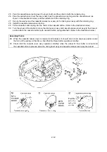
Remove the three screws securing the under cover assy (refer to the bottom-view diagram below), and then
lift off the upper cover assy.
3.
Disconnect the six connectors, and then remove the upper cover assy.
Note
1.
If the carriage is not moved to its removal position, the upper cover assy cannot be removed
T-1
MESH PTN
T-2
DECOMPOSE POSS
DECOMPOSE POSS
Содержание E-100
Страница 1: ... 3 2002 ...
Страница 4: ...1 1 1 TECHNICAL DIAGRAMS ...
Страница 6: ...1 3 4 CONTROL SYSTEM BLOCK DIAGRAM ...
Страница 23: ...2 15 3 LEAD WIRE ARRNGEMENT For details refer to the instructions of wiring ...
Страница 31: ...3 3 Main PC board ASSY REG board ASSY Sensor board ASSY ...
Страница 32: ...4 0 IV 1 PARTS CATALOGUE 4 1 2 OTHER PARTS 4 3 ...
Страница 34: ...4 2 ...
Страница 36: ...4 4 ...
Страница 37: ...E 100 E 100P E 100M XXXXXXX ...


