2-7
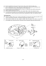
33. Remove the four screws and the main PC board assy screw, and then remove the middle cover.
34. Remove the three screws, and then while pressing on the composite spring section of the upper cover assy,
remove the liquid crystal display. Next, remove the main PC board assy.
35. Remove the operation keys.
36. Remove the cassette guide from the upper cover assy.
Disassembly Points
36. Since the cassette guide is snapped into place, release the hooks on the guide to remove it.
Содержание E-100
Страница 1: ... 3 2002 ...
Страница 4: ...1 1 1 TECHNICAL DIAGRAMS ...
Страница 6: ...1 3 4 CONTROL SYSTEM BLOCK DIAGRAM ...
Страница 23: ...2 15 3 LEAD WIRE ARRNGEMENT For details refer to the instructions of wiring ...
Страница 31: ...3 3 Main PC board ASSY REG board ASSY Sensor board ASSY ...
Страница 32: ...4 0 IV 1 PARTS CATALOGUE 4 1 2 OTHER PARTS 4 3 ...
Страница 34: ...4 2 ...
Страница 36: ...4 4 ...
Страница 37: ...E 100 E 100P E 100M XXXXXXX ...


