2-11
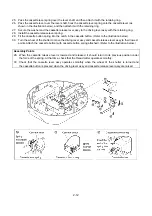
19. From the bottom of the under cover assy, secure the base plate assy with the three screws.
20. Secure the thread cutter assy to the base plate assy with the screw.
21. Attach the E3 retaining ring to the thread cutter lever shaft of the base plate assy.
22. Secure the two thread cutter links to the thread cutter assy with the two E2 retaining rings.
23. Secure the thread cutter lever assy to the thread cutter links with the E2 retaining ring, and then secure it to
the thread cutter lever shaft with the E3 retaining ring.
24. Secure the thread cutter switch assy to the base plate assy with the screw.
Assembly Points
24. It is necessary to adjust the installation angle of the thread cutter switch assy. Adjust it so that the switch is
off when the thread cutter lever is lowered, and the switch is on when the lever is slowly brought back up.
(The amount that it is pressed after the switch is turned on is 1 to 2 mm.)
Содержание E-100
Страница 1: ... 3 2002 ...
Страница 4: ...1 1 1 TECHNICAL DIAGRAMS ...
Страница 6: ...1 3 4 CONTROL SYSTEM BLOCK DIAGRAM ...
Страница 23: ...2 15 3 LEAD WIRE ARRNGEMENT For details refer to the instructions of wiring ...
Страница 31: ...3 3 Main PC board ASSY REG board ASSY Sensor board ASSY ...
Страница 32: ...4 0 IV 1 PARTS CATALOGUE 4 1 2 OTHER PARTS 4 3 ...
Страница 34: ...4 2 ...
Страница 36: ...4 4 ...
Страница 37: ...E 100 E 100P E 100M XXXXXXX ...


