24
Section D – Electrical Components
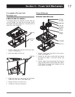
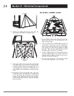
SCREWS
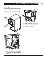
Remove five Phillips head screws each from the
8.
lower right and left sides of the cabinet cover.
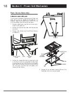
STABILIzER
PLATES
Gently spread lower left and right sides of the cabinet
9.
cover apart and raise a few inches to allow the left
and right stabilizer plates to be removed. Take care
not to damage or tear the gasket. Tilt the bottom front
of the cabinet cover forward and up while raising the
cover.
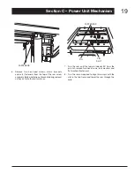
Grasping the front and rear edges of the cover, raise
10.
it up a few inches and allow it to rest temporarily
on the four locator pins. Remove the left and right
stabilizer plates. Again grasp the front and rear edges
of the cover and lift it off the unit, tilting it forward and
back as required.
RE-INSTALL CABINET COvER
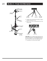
PINS
1. To re-install the cabinet cover, lift the cover over the
top of the unit and allow it to rest temporarily on the
top of the locator pins.
Insert the right and left stabilizer plates but do not
2.
secure them in place (they will rest temporarily on
top of the ram). Gently move the cover so that the
front and rear pins slide into their respective rubber
grommets. Make sure the sound-deadening material
fits properly down the sides of the cabinet.
Using six Phillips head screws (front and rear), secure
3.
the three stabilizer plates to the cabinet. NOTE: The
stabilizer plates rest below the front and rear cross-
members (see illustration above).
Re-install the bag storage, control panel, cabinet
4.
cover, bucket and door, etc., in reverse order.


