20
Section C – Power Unit Mechanism
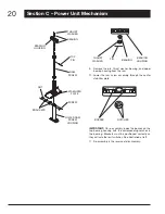
NUT
BRACKETS
TOP
PIN
SCREW
BEARING
HOUSING
LOWER RAM
SCREW
HOUSING
BEARING
RAM
SCREW
THRUST
WASHER
STABILIzER
PLATE
THRUST
WASHER
BEARING
HOUSING
PIN
BEARING
Remove the pin, thrust washer, bearing, and upper
9.
bearing housing from the ram.
Lower the ram screw assembly through the center
10.
stabilizer plate.
BOSSES
NOTCHES
IMPORTANT:
On re-assembly, index the bosses on the
top bearing housing with the corresponding notches in
the bearing. Brackets must be positioned correctly as
they activate the limit switches. See illustration at left.
Re-assembly is the reverse of disassembly.
11.


