briwatec TOPAS E350 V Скачать руководство пользователя страница 14

Functional description 

B125 06/16 Rev.1  


TOPAS E350V-E600V 


           14 


5.2


Construction 

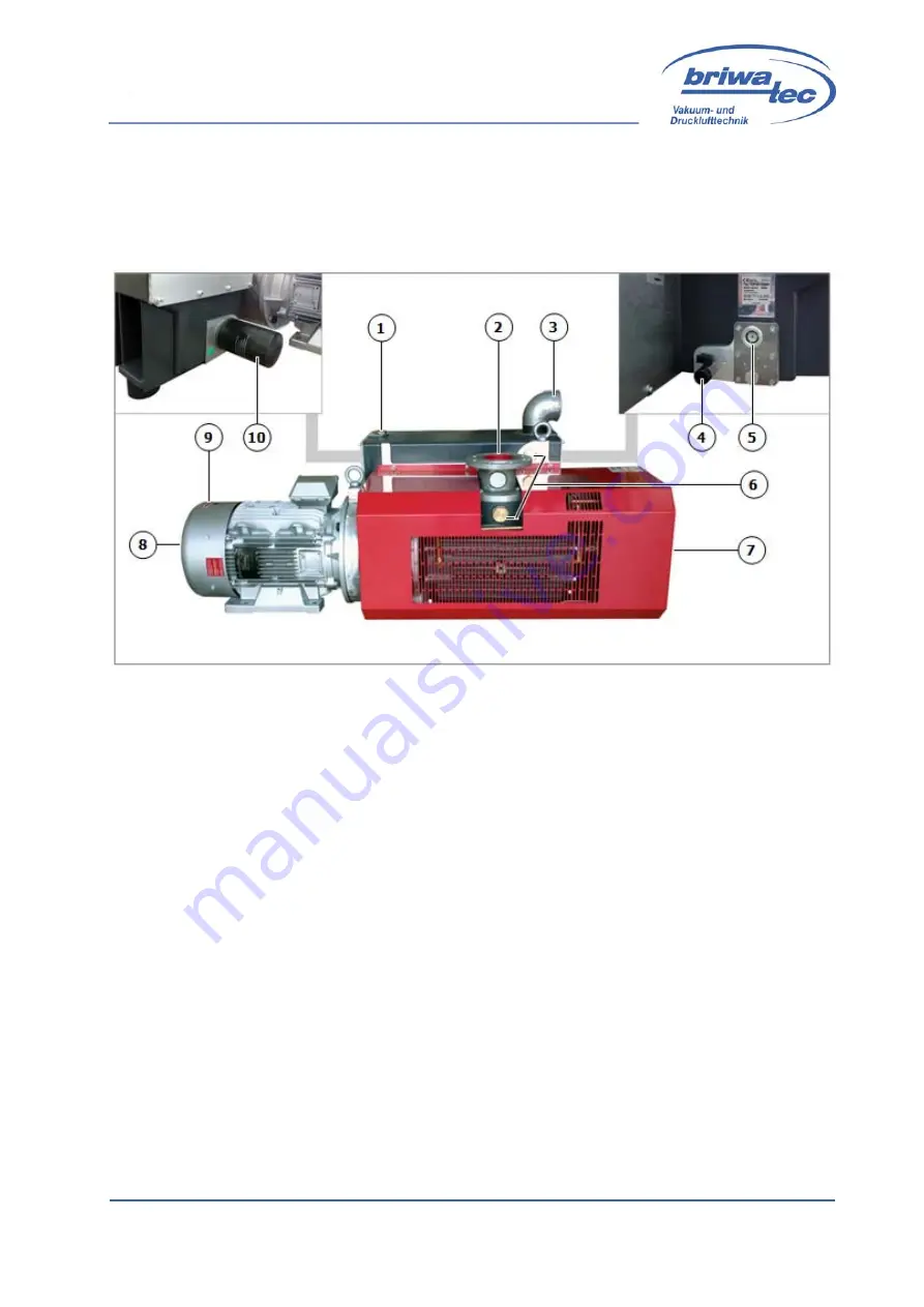
The TOPAS rotary vane vacuum pump consists of the following major compo-
nents: 


Fig. 4  TOPAS main components 

 
1.


Oil filling point 

2.


Vacuum connection 

3.


Exhaust air outlet 

4.


Oil drain valve 

5.


Oil sight glass 

6.


Connection for starting discharge (option with magnetic valve) 

7.


Cooling air inlet 

8.


Cooling air inlet 

9.


Motor with direction of rotation arrow 

10.


Oil filter 


Содержание TOPAS E350 V

Страница 1: ... Schönauer Str 62 79669 Zell i W Germany Telephone no 49 0 7625 918 868 0 Fax no 49 0 7625 918 868 33 email info briwatec de Website www briwatec de Managing Directors Markus Britsche Michael Wagner District court Freiburg i Br HRB 700368 VAT number 11088 10922 Value added tax identification no DE 814 742 383 ...

Страница 2: ...1 4 Technical specifications 12 4 1 Type plate 12 4 2 Noise emissions 12 5 Functional description 13 5 1 Conditions of use 13 5 2 Construction 14 5 3 Function 15 6 Transport storage 16 6 1 Safety instructions for transport 16 6 2 Lifting and transporting the machine 16 6 3 Storage 16 7 Commissioning 17 7 1 Setup 17 7 2 Installation 18 7 3 Commissioning 19 8 Operation 20 9 Maintenance 21 9 1 Air fi...

Страница 3: ...idelines and safety regula tions They must also be respected 2 2 Limitation of liability All information and advice in these instructions has been compiled in accordance with current standards and regulations the state of technology and our knowledge and experience The company briwatec GmbH assumes no liability for damage due to Failure to follow the instructions Improper use Use of untrained staf...

Страница 4: ...st are hazardous waste After replacement wearing parts must be disposed of according to national laws 2 5 Service For service questions please contact the company briwatec GmbH as follows briwatec GmbH Tel 49 0 7625 918 868 0 Fax 49 0 7625 918 868 33 Schönauer Str 62 79669 Zell i W Germany info briwatec de www briwatec de For faster processing of your requests we ask you to have the following data...

Страница 5: ...Introduction B125 06 16 Rev 1 TOPAS E350V E600V 5 2 6 CE Declaration of Conformity Fig 1 CE Declaration of Conformity ...

Страница 6: ...liability and warranty will be rejected by the company briwatec GmbH 3 2 Description of safety instructions Safety instructions refer to specific hazards They are marked by symbols in this manual There are four principles that must be considered in the design of safety infor mation Severity of the risk signal word Type and source of danger description Result of failure to comply Prevention measure...

Страница 7: ...ese instructions NOTE This symbol indicates an important fact It provides valuable information about installation use or maintenance RECYCLING This symbol indicates useful information for disposal Materials are separated and disposed of separately In addition the requirements for the disposal of lubricants oils and fats and other additives are to be considered 3 4 Safety and information signs on t...

Страница 8: ...61 310 1 READ THE INSTRUCTIONS FOR USE Mandatory reading of the instructions for use ISO 7000 0419 PROHIBITED Protective grids and safety devices must not be removed WARNING Danger of death due to electricity Indicates a potentially hazardous situation which can result in death or serious injury from electrical shock if not avoided WARNING Outlet of hot or dangerous gases HOT SURFACE Indicates a p...

Страница 9: ...he operation of the machine must only be performed by trained or skilled per sonnel The operator must be familiar with the basic regulations on occupational safety and accident prevention and must be familiar and trained in the operation of the machine Before switching on the machine the user must have read and understood this manual 3 6 Definition of terms have been informed by the operator in a ...

Страница 10: ...achine in a technically perfect condition Do not operate the machine in a partially assembled condition The machine must only be operated at ambient temperature and suction temperature between 12 and 40 C At temperatures outside this range please contact us The machine may be used to convey compress or suction the following media Air The suctioned air may contain water vapour but no water and othe...

Страница 11: ...in operation or provided with protection against being touched No people may be endangered by the free suction or ejection of the fluids Dangers from electrical energy are excluded The operator must be aware of the applicable safety regulations and conduct a risk assessment to identify additional risks posed by specific working conditions at the machine s installation location This must be impleme...

Страница 12: ...ice consultations the type description year of manufacture and serial number must be available Fig 3 Type plate 4 2 Noise emissions The following noise emissions were determined for operation at 50 60 Hz Type Average sounds pressure level dB A 50 Hz 60 Hz TOPAS E350V 75 76 TOPAS E400V 75 77 TOPAS E500V 75 77 TOPAS E600V 76 78 The values were calculated on the basis of DIN EN ISO 3744 3 dB A ...

Страница 13: ...n n TOPAS E350V D186 TOPAS E400V D187 TOPAS E500V D188 TOPAS E600V The suctioned air may contain water vapour but no water and other fluids Ag gressive or combustible gases and vapours may not be suctioned No hazardous additives e g combustible or explosive gases or vapours or aggressive gases may be suctioned Operation in rooms with an explosion risk is not permitted The ambient temperature must ...

Страница 14: ...ts of the following major compo nents Fig 4 TOPAS main components 1 Oil filling point 2 Vacuum connection 3 Exhaust air outlet 4 Oil drain valve 5 Oil sight glass 6 Connection for starting discharge option with magnetic valve 7 Cooling air inlet 8 Cooling air inlet 9 Motor with direction of rotation arrow 10 Oil filter ...

Страница 15: ...s with a consequence of different volumes which permit the gen eration of an underpressure and a flow rate 1 Suctioning start of filling 2 max filling volume 3 compression During phase 1 the oil for lubrication compression and cooling is injected It can be injected directly or piped in by an oil filter before injection The medi um oil mixture is conveyed from the housing via the pressure valve to ...

Страница 16: ...aging is intended to protect the individual components prior to assembly against shipping damage corrosion and other damage Therefore do not destroy the packaging until just prior to installation Before every long transportation remove the oil from the pump ENVIRONMENTAL DAMAGE CAUSED BY IMPROPER DISPOSAL Packaging materials are valuable commodities and can often be reused or prepared for recyclin...

Страница 17: ... reservoir cover see Fig 6 The TOPAS E350V to E600V can only be operated error free in a horizontal setup location The pumps must not be tilted The setup of the vacuum pump on solid ground is possible without anchorage The vibrations from these rotary vane vacuum pumps are minimal In the case of setup on a lower construction we recommend anchorage via elas tic buffer elements The vacuum pumps are ...

Страница 18: ...d 2 Fill in lubrication oil for oil quantity see Chap 9 2 page 21 at the oil filling point item 1 of the oil reservoir filling height middle of oil sight glass item 5 then close the filling point 3 The electrical motor data is indicated on the type plate chap 4 1 page 12 and on the motor data plate The motors comply with DIN EN 60034 and are in safety class IP 55 and insulation class F The corresp...

Страница 19: ... conditions Momentary overcurrent can occur during cold start of the blower 7 3 Commissioning 1 Briefly start the motor to check the direction of rotation item 9 direction of rotation arrow Fig 4 page 14 2 After possibly correcting the direction of rotation restart the motor and stop it again after approx 2 minutes to refill missing oil according to the oil level in the sight glass on the filling ...

Страница 20: ...d be hazardous to health Therefore you must ensure good ventilation of the installation room HOT SURFACE Surface temperatures over 70 C In the hot operating state the surface temperatures of components can increase to above 70 C Risk of burns Avoid touching the components Wear protective gloves Before starting operation the correct installation of the machine the installation and commissioning tes...

Страница 21: ...be cleaned at the same time 9 2 Oil change The first oil change must be performed after 1 5000 operating hours All other oil changes are as follows 3 000 hours for synthetic oil MV46S 4 000 hours for synthetic oil BW100S Perform an oil change at least once per year In the case of severe dirt contamination the oil change intervals must be reduced accordingly INFORMATION The indicated oil change int...

Страница 22: ...t glass 3 Oil drain valve with drain tap Open the oil drain valve 3 and allow oil to drain out of the pump Lift up the pump tilt it a little on the motor side to speed up the drainage process Then close the oil drain valve 3 again Fill up the emptied pump with new oil via the oil filling opening 1 up to the middle of the oil sight glass 2 amount of oil 10 l Then reclose the oil filling opening wit...

Страница 23: ...he new oil filter Fig 9 Oil filter The oil filter must be changed on every oil change 9 4 Filter element air de oiling element The filter element becomes contaminated less or more quickly depending on the level of contamination of the suctioned medium The filter element cannot be reused It is recommended to replace the filter ele ment on each oil change Fig 10 Air de oiling element ...

Страница 24: ...RMATION There can be mounted up to six filter elements Insertion of the new filter element Position the nose of the filter element correctly in the seat of the pressure chamber so that the O ring 7 lies on side A of the seat Reattach the clamp unit 5 and screw it tight 3 so that the O ring 7 presses against side A After inserting the new filter element and before attaching the closing plate 2 and ...

Страница 25: ...ace it when necessary Fig 12 Suction grid Removal Remove the suction flange 3 Remove the grid 1 and clean it Remove the counterflange 4 Refit in the reverse order 9 6 Coupling The coupling ring is subject to wear depending on the conditions of use number of stops starts temperature etc Check the status of coupling ring in the maintenance during an oil change Re place when necessary to do so remove...

Страница 26: ... same time Fig 14 Lip seals Removal of housing cover on the motor side Remove the motor unit Remove the half coupling of the rotor shaft Remove the housing cover Check the condition of the protective shaft sleeve 2 replace if necessary or move the lip seal Remove the lip seal 1 and insert the new one To do so use a tool that 4nsures the verticality of the lip seal to the rotor axis The main lip is...

Страница 27: ...s ballast is equipped with an air filter that must be replaced at every oil change Fig 15 Gas ballast Removal Remove the cap 1 Replace the filter element 2 9 9 Automatic oil back suction Fig 16 Oil back suction Oil back suction is located in the compartment below the filter elements ...

Страница 28: ...l separator the float 3 must rise Restart the pump The filled up oil must be suctioned the oil level in the filter elements drops If there is a clear leakage of oil after loosening the access plate this means the nozzle 2 is blocked Loosen the screw fitting 1 and rinse the nozzle 2 9 10 Oil level monitoring optional Optionally a float switch or oil level switch can be fitted to trigger an alarm wh...

Страница 29: ...ghten if necessary Check the terminal boxes and cable insertion opening for leaks and reseal if necessary Clean the ventilation slits of the machine and the cooling fins of the motor Clean the air grid of the oil cooler Annual maintenance Check the coupling for wear see Chap 9 6 page 25 Maintenance according to the level of contamination Clean the filter suction air see Chap 9 1 page 21 Maintenanc...

Страница 30: ...r is too high Optimize the air removal 2 The suction power is insufficient Cause Remedy The suction filter is contaminated Clean or replace the suction filter The suction pipe is too long or too narrow Use a larger pipe cross section remove bottlenecks Leak in the pump or in the system Check the pump and the pipes for pressure loss 3 Final pressure max vacuum is not reached Cause Remedy Leak on th...

Страница 31: ...e air de oiling element The air de oiling element is leaking Check the O ring 6 Vacuum pump produces unusual noise Cause Remedy The pump housing is worn out chatter marks Repair to be performed exclusively by manufacturer or authorized repair shop The vacuum regulation valve vibrates if present Replace the valve The blades are damaged Replace the blades Vacuum pump or its oil is too cold Check it ...

Страница 32: ... Fig 5 TOPAS functional diagram 15 Fig 6 Structural diagram 17 Fig 7 Connections to three phase network 18 Fig 8 Changing the oil 22 Fig 9 Oil filter 23 Fig 10 Air de oiling element 23 Fig 11 Filter element 24 Fig 12 Suction grid 25 Fig 13 Coupling ring 25 Fig 14 Lip seals 26 Fig 15 Gas ballast 27 Fig 16 Oil back suction 27 Fig 17 Float switch for oil back suction 28 Fig 18 Oil level monitoring 29...

Отзывы: