


6.13.
Check that the telescopic flue slides freely.
Fasten together the flue terminal and any extension
sections intended to pass through the wall, in a simi-
lar manner to 6.6. Do not fix the telescopic length at
this stage!
6.14.
Push fit the flue terminal assembly onto the last
flue section of the air box/flue assembly and drill the
two securing holes. Do not screw together at this
stage! Consideration must be given to the position of
these securing screws on the section which will be
fed back through the hole in the wall. Where access
to a fixing screw will not be possible when the flue is
installed, drill a new securing hole position, at the
same height, as far as possible from the other screw.
6.15.
Remove the flue terminal assembly and push
the telescopic end in to give the shortest length.
6.16.
Slide the air box/flue assembly onto the boiler
flue tube and push down until the assembly bottoms
out on the flue tube.
6.17.
Feed the flue terminal assembly back through
the hole in the wall from outside the property and
push fit onto the flue section within the property.
Take care to prevent dirt falling onto the greased
seals!
6.18.
Align the fixing holes previously drilled in 6.14
and temporarily fix with one screw.
6.19.
From outside the property pull the telescopic
end to the required length so that the inside edge “A”
(See fig 6a) of the terminal seal locating slot is flush
with the outside of the wall. Take care to avoid sharp
edges- wear gloves!
6.20.
Place temporary packing underneath the white
section of the flue terminal to support it.
6.21
. Remove the fixing screw added in 6.18.
6.22.
Remove the flue terminal assembly by pushing
the assembly forward, from within the property, to
release it from the air box/flue assembly. Take care
not to alter the set length!
6.23.
Fix the telescopic length. Using the fixing holes
as a guide , drill through with the 2.8mm drill bit pro-
vided in the kit and fasten the terminal using the two
self tapping screws provided.
6.24.
Re-fit the flue terminal assembly and secure
using two self tapping screws.
6.25.
Continue fitting as described in 6.46.
Method 2.
Note: The sliding section of the telescopic flue termi-
nal must be fixed using the self tapping screws pro-
vided. The length can be set by measurement as
described in 6.36 to 6.43 or by pushing the whole
boiler/flue assembly into position and setting the slid-
ing terminal to the correct length. The terminal can
then be fixed by pulling the whole boiler/flue assem-
bly back far enough to drill through the pilot holes
and fasten with the self tapping screws as described
in 6.23. When using this method ignore 6.36, 6.39,
6.42, 6.43.
6.26
. Remove the 4 inch (103mm) conventional flue
spigot and gasket from the flue outlet plate by undo-
ing the three screws.
Note: To create a good seal between the boiler
and air box assembly only use the flue ring gas-
ket supplied within the RS flue kit.
6.27.
Position the new flue ring gasket on the flue
outlet plate and clamp the flue tube in place using
the flue tube retainer and screws as shown in fig 4.
6.28.
When fitting an elbow directly to the air box,
push the elbow fully down on the air box collar and
rotate the elbow to the required position (left, rear or
right) ensuring that the air tube is pointing to the
front of the appliance as shown in fig 4.
6.29.
Using the fixing holes as a guide, drill through
with the 2.8mm drill bit provided in the kit and fasten
the elbow to the air box collar using the two self tap-
ping screws provided.
6.30.
Where access to a fixing hole is not possible
(e.g. left and right flue options), drill a new securing
hole position, at the same height, as far as possible
from the other screw.
6.31.
When fitting a vertical extension attach the
extension to the air box and then attach the elbow to
the extension in a similar manner to 6.28 to 6.30
6.32.
Add any further extensions/elbows, in a similar
manner to 6.28 to 6.30, until the last section before
exiting the wall is reached.
6.33.
Move the boiler to the desired position.
6.34.
Slide the air box/flue assembly onto the flue
tube and push down until the assembly bottoms out
on the flue tube. This must leave a minimum air gap
of 15mm between the air box and the flue outlet
plate. The nominal air gap will be 27mm when an
elbow is fitted directly to the air box and 17mm when
6
185mm
L
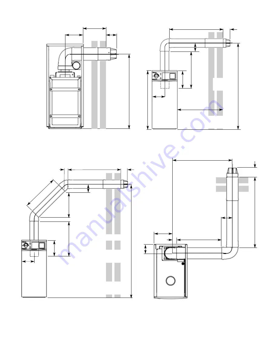
Fig. 2a. Low level horizontal flue with 90° bend
Total straight
length of L
must not
exceed
2500mm
Fig. 2c. High level horizontal flue with two 45° bends
Fig. 2d. Side exit of flue with two 90° Bends
Fig. 2b. High level horizontal flue with one 90° bend
100mm
L1
119
218
H
100mm
855
754mm
185
L2
Total straight length
of L1 + L2 must not
exceed 1500mm
Distance from centre of
boiler to centre of flue
terminal (S)
S = 185 +L1
185mm
66
100
mm
L2
100mm
L1
Y
104
H
L3
42
100mm
185mm
218
58
L2
L1
119
S
Fig. 2. Side discharge flue systems.
Centre of flue
terminal to floor
H = 754 + L1
Total straight length
of L1 + L2 must not
exceed 2500mm
Total straight length of
L1 + L2 + L3 must not
exceed 2500mm
H = 799 + L1 + Y
Y=353 (500mm extension)
or
Y=707 (1000mm extension)
L
Front view
Front view
Front view
Plan view
3
Содержание RD 628
Страница 34: ...34 1 2 3 4 7 5 6 8 9 10 11 12 4 15 13 16 19 14 17 18 20 22 23 21 ...
Страница 45: ...45 ...
Страница 46: ...46 ...
Страница 47: ...47 ...
Страница 51: ......
Страница 53: ......
Страница 55: ...L2 0mm ...
Страница 57: ......
Страница 58: ...RD 628 USER INSTRUCTIONS CUSTOMER CARE GUIDE G C NUMBER 47 108 14 ...
Страница 71: ...14 ...


