background image

NOTE:

Read the entire instruction manual before starting the installation. These instructions must be affixed on or adjacent to the boiler.

This symbol

indicates a change since the last issue.

ama

ASME

®

A88177

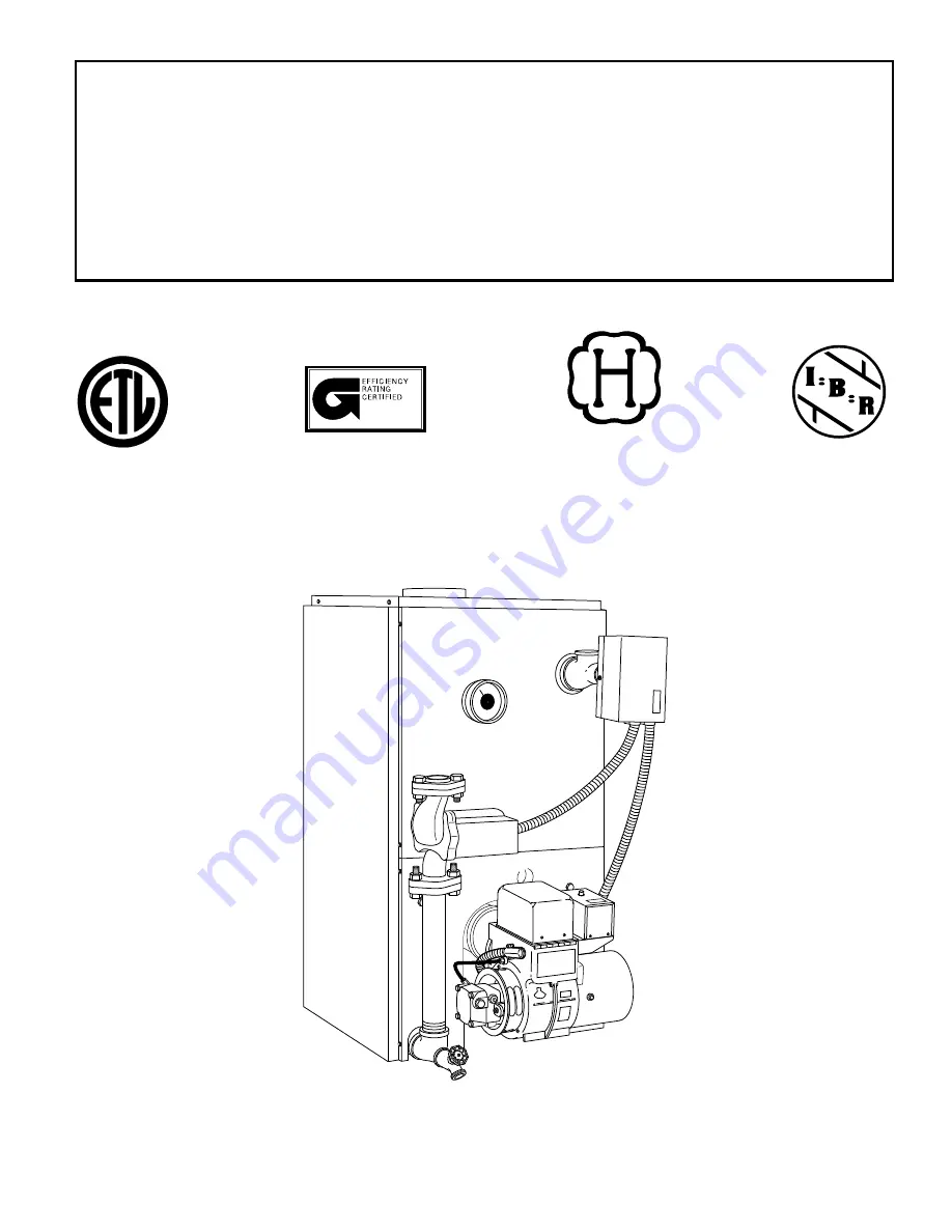
MODEL BW4/BW5

Installation, Start-Up, and Operating Instructions

BW4
BW5

Oil-Fired
Cast Iron Hot Water Boilers
Sizes 74,000 through 239,000
Series A

Form:

IM-BW4A-03

Cancels:

IM-BW4A-02

Printed in U.S.A.

5-98

Catalog No.

63BW-4A0

Содержание BW4

Страница 1: ... adjacent to the boiler This symbol indicates a change since the last issue ama ASME A88177 MODEL BW4 BW5 Installation Start Up and Operating Instructions BW4 BW5 Oil Fired Cast Iron Hot Water Boilers Sizes 74 000 through 239 000 Series A Form IM BW4A 03 Cancels IM BW4A 02 Printed in U S A 5 98 Catalog No 63BW 4A0 ...

Страница 2: ...15 Relief Valve Provided 15 Expansion Tank Not Provided 15 Diaphragm Type Expansion Tank Not Provided 15 Air Eliminating Fitting Air Purger Not Provided 15 Main Air Vent for Downflow Systems or Diaphragm Type Expansion Tank Not Provided 15 Aquastat Relay Control Provided 15 Automatic Fill Valve Not Provided 15 Drain Valve Provided 15 Circulating Pump Provided 15 FILLING BOILER 15 16 How a Hot Wate...

Страница 3: ...te air supply for complete combustion 8 Follow a regular service and maintenance schedule for efficient and safe operation 9 Keep boiler area clean and free from combustible materials gasoline and other flammable vapors and liquids WARNING Use only number 1 or number 2 fuel oil having commercial standard grade CS 12 48 Do not use gasoline kerosene crankcase oil or any oil containing gasoline A fai...

Страница 4: ...Engineers A S M E Section IV Standards for cast iron heating boilers They are capacity rated in accordance with the code of the Hydronics Institute Fig 1 Dimensional Drawing and Boiler Ratings and Capacities Oil Fired Hot Water Boiler Ratings BOILER MODEL NUMBER NO OF SECTIONS INPUT MBH HEATING CAPACITY MBH NET I B R RATING MBH MAXIMUM FIRING RATE GPH TYPICAL CHIMNEY DIMENSIONS IN Without Tankless...

Страница 5: ... where passage is required to access another side for cleaning servicing inspection or replacement of any parts that normally may require such attention Boilers must be installed at least 6 in from combustible materials on all sides and above Allow at least 24 in front clearance for servicing Allow at least 18 in right side clearance for servicing boilers equipped with a tankless coil 6 FRESH AIR ...

Страница 6: ...ATED IN UNCONFINED SPACE An unconfined space is defined as a space with volume not less than 50 cu ft per 1000 Btuh of total input rating of all appliances installed in that space If boiler is in an open area unpartitioned basement in a conventional house air that leaks through cracks around doors and windows will usually be adequate to provide air for combustion The doors should not fit tightly C...

Страница 7: ...ure 2 When communicating with the outdoors through vertical ducts each opening shall have a minimum free area of 1 sq in per 4000 Btuh of total input rating of all equipment in the enclosure 3 When communicating with the outdoors through horizontal ducts each opening shall have a minimum free area of 1 sq in per 2000 Btuh of total input rating of all equipment in the enclosure 4 When ducts are use...

Страница 8: ...harge pipes between such safety valves and the atmosphere Installation of safety relief valve shall conform to requirements of the ANSI ASME Boiler and Pressure Vessel Code Section IV The manufacturer is not responsible for any water damage Connect a drain line of the same pipe size 3 4 in to carry any water away to a drain 3 Connect supply and return lines to boiler Both supply and return lines s...

Страница 9: ...PANSION TANK Fig 9 Forced Hot Water Typical Piping with Zone Control Valves A95599 FRONT TO ZONE 1 SUPPLY MAIN TO ZONE 2 SUPPLY MAIN ELL TEE Fig 10 Piping Arrangements for Boiler When Used in Connection with Refrigeration System A96153 C VALVES A B OPEN FOR HEATING CLOSE FOR COOLING TO SYSTEM A B D WATER CHILLER VALVES C D CLOSE FOR HEATING OPEN FOR COOLING 9 ...

Страница 10: ...t at boiler with a vertical pipe and then an elbow 2 Install draft regulator making it horizontal 3 When regulator is in place start at chimney and work back to regulator 4 Join the 2 sections with a drawband The horizontal pipe must slope up toward chimney at least 1 4 in per ft It must not leak and must be firmly supported 5 Join sections with at least 2 sheet metal screws 6 Support every second...

Страница 11: ...CT MUST HAVE AN UNOBSTRUCTED TOP OPENING MUST BE AT LEAST 4 IN THICK AND BE TIGHT BALANCED WEIGHT CRIMPED END ALTERNATE POSITIONS TOP TOP MUST SLOPE UP AT LEAST 1 4 IN PER FOOT OF HORIZONTAL RUN TIGHT CLEAN OUT DOOR SEALED IN THIMBLE TIGHT SMOOTH CORRECTLY SIZED DRAWBAND LAST PIECE INSTALLED DRAFT REGULATOR VANE A95601 Fig 11 Typical Chimney Requirements 11 ...

Страница 12: ...competent electrician do this job Boiler controls are all wired at the factory All that is required is to connect a 115 v electric supply and thermostat wires to aquastat relay Run a separate circuit from a separate overcurrent protective device in electrical service entrance panel This should be a 15 amp circuit Locate a shutoff switch at boiler It must be turned OFF during any maintenance Solder...

Страница 13: ...NE NEUTRAL 24 V THERMOSTAT FIELD WIRING OIL BURNER MOTOR L8148A AQUASTAT IGN TRANS B W CIRCULATOR B W B W W B O B B R4184D RELAY Y Y CAD CEL 1K1 JUMPER 1K 1K2 B2 C2 C1 ZC F F ZR B1 L2 T T T T G GND L1 HOT L2 L1 L2 B1 B2 C1 B R ZR B R W ZC C2 HIGH LIMIT 1K2 LOW LIMIT CIRCULATOR COLOR CODE BK BLACK O ORANGE Y YELLOW R RED W WHITE 1K1 1K A R LINE VOLTAGE CLASS II 24 VOLTS T T L2 L1 3 F F B 3 T T C1 C...

Страница 14: ...ig 14 Boiler With Tankless Heater Coil With Optional Field SWG Power Venter and CK 62 Control Kit C1 F F G L1 L2 B R 3 T T C2 B1 B2 M T3 T2 T1 M N L1 RELAY CK KIT JUNCTION BOX WMO 1 SECONDARY SAFETY SWITCH SPILL SWITCH SWG POWER VENTER MOTOR L1 L2 120 VAC W BK BK BK BK PPC 4 N O W W W W W W W Y Y CAD CELL R4184 RELAY IGNITION TRANSFORMER OIL BURNER MOTOR BK BK BK BK BK BK W BK BK W L8148A AQUASTAT...

Страница 15: ... any other convenient place in supply or return line PROCEDURE 4 AIR ELIMINATING FITTING AIR PURGER NOT PROVIDED An air purger is used to remove air from system It is installed in supply line It eliminates air from water before it reaches radiators and bleeds off this air PROCEDURE 5 MAIN AIR VENT FOR DOWNFLOW SYSTEMS OR DIAPHRAGM TYPE EXPANSION TANK NOT PROVIDED Before a system is filled with wat...

Страница 16: ... and formation of soot will occur in heating unit In buildings of conventional frame brick or stone construction without utility rooms basement windows or stair doors infiltration is normally adequate to provide air for combustion and operation of barometric draft control The room should be isolated from any area served by exhaust fans Do not install exhaust fans in this room See Fresh Air for Com...

Страница 17: ...2 181 V1 1 16 7 32 to 9 32 239 A95603 L1 OR V1 HEAD NOZZLE ELECTRODE DIMENSION N SEE BELOW 5 32 GAP 5 16 ABOVE DIMENSION H SEE BELOW Fig 19 Beckett Burner Variable Head Dimensional Relationships for 181 and 239 Size Units A95606 5 13 16 5 7 32 6 1 2 1 3 4 4 15 32 1 5 8 Fig 17 Beckett Burner Setting Variable V1 Head A95604 LOCATION OF HEAD AT 0 POSITION ON ADJUSTING PLATE WITNESS MARK HOLD DOWN SCR...

Страница 18: ...ture falls a few degrees Finally set thermostat for desired temperature Special conditions in home and location of thermostat will govern this setting NOTE Do not start burner unless all cleanout doors are secured in place MAINTENANCE To assure trouble free operation we recommend that flue passages burner combustion chamber area target wall and fire door insulation burner adjustment and operation ...

Страница 19: ...el and separate the 2 panels enough for side jacket panel to slip off the Z bars on collector top 4 Remove 2 brass wing nuts holding flue collector top Remove top jacket support bracket and 2 Z bars and collector top 5 Check gasket on underside of flue collector and replace as necessary 6 Remove lower front jacket panel 4 sheet metal screws and 2 cap nuts 7 Remove oil burner 3 cap screws OR Remove...

Страница 20: ...s the same control setting minus 10 The RB break and RW make temperature is the set point temperature plus the difference between differential setting and 10 The low limit control fires burner to maintain boiler water temperature at low limit setting set point plus adjustable differential setting minus 10 While boiler water temperature is below low limit setting circulator is prevented from operat...

Страница 21: ...rner cleaned and readjusted Burner may not be firing at proper rate Check nozzle size it there is any doubt Have burner adjusted Burner may be short cycling Short cycling too frequent off and on of burner causes sooting If boiler and or burner becomes dirty at frequent intervals correct the dirt condition then also correct the control setting or other cause of short cycling Check thermostat heat a...

Страница 22: ...77 425 00 278 Collector Flue 12 146 93 064 146 93 064 146 93 064 Gasket 13 146 27 020 146 27 020 146 27 020 Tankless Heater Coil 14 146 19 001 146 19 001 146 19 001 Tankless Heater Cover Plate 15 146 95 105 146 95 105 146 95 105 3 8 in 16 X 3 4 in Hex Head Cap Screw 10 15A 146 95 113 146 95 113 146 95 113 3 8 in 16 X 1 1 2 in Stainless Steel Studs 10 req d 15B 146 95 114 146 95 114 146 95 114 3 8 ...

Страница 23: ...425 00 241 425 00 242 425 00 243 Right Side Panel 4 425 00 270 425 00 270 425 00 270 Upper Front Panel 5 425 00 272 425 00 272 425 00 272 Lower Front Panel 6 425 00 261 425 00 262 425 00 263 Left Side Panel 7 425 00 273 425 00 273 425 00 273 Z Bars 146 95 074 146 95 074 146 95 074 No 10 X 1 2 in Sheet Metal Screw 425 00 286 425 00 287 425 00 288 Complete Jacket Not illustrated A95613 2 1 6 5 3 4 7...

Страница 24: ...33 00 521 Aquastat Control without Tankless Heater 2B 146 62 022 146 62 022 146 62 022 Aquastat Control with Tankless Heater 3 146 23 003 146 23 003 146 23 003 Gage 4 146 26 047 146 26 047 146 26 047 Circulator 146 22 011 146 22 011 146 22 011 Relief Valve 146 20 007 146 20 007 146 20 007 Barometric Draft Control 146 22 000 146 22 000 146 22 000 Drain Valve 146 55 003 146 55 003 146 55 003 Flue Br...

Отзывы: