


tion and screwing through with the self tapping
screws provided.
6.2.
The following guide explains two possible meth-
ods of assembly.
The boiler can be fixed in position and the flue fed
back through the wall (Method 1), or the flue can be
assembled onto the boiler and the boiler /flue then
pushed back against the wall to feed the flue through
the wall (Method 2). In both cases the telescopic
flue must be securely fastened at the required length
using the two self tapping screws provided.
Method 1.
6.3.
Remove the 4 inch (103mm) conventional flue
spigot and gasket from the flue outlet plate by undo-
ing the three screws.
Note: To create a good seal between the boiler
and air box assembly only use the flue ring gas-
ket supplied within the RS flue kit.
6.4.
Position the new flue ring gasket on the flue out-
let plate and clamp the flue tube in place using the
flue tube retainer and screws as shown in fig 4.
6.5.
When fitting an elbow directly to the air box,
push the elbow fully down on the air box collar and
rotate the elbow to the required position (left, rear or
right) ensuring that the air tube is pointing to the
front of the appliance as shown in fig 4.
6.6.
Using the fixing holes as a guide , drill through
with the 2.8mm drill bit provided in the kit and fasten
the elbow to the air box collar using the two self tap-
ping screws provided. Where access to a fixing hole
is not possible (e.g. left and right flue options), drill a
new securing hole position, at the same height, as
far as possible from the other screw.
6.7.
When fitting a vertical extension attach the exten-
sion to the air box and then attach the elbow to the
extension in a similar manner to 6.5 to 6.6.
6.8.
Add any further extensions/elbows in a similar
manner to 6.5 to 6.7, until the last section before
exiting the wall is reached.
6.9.
Slide the air box/flue assembly onto the flue tube
and push down until the assembly bottoms out on
the flue tube. This must leave a minimum air gap of
15mm between the air box and the flue outlet plate.
The nominal air gap will be 27mm when an elbow is
fitted directly to the air box and 17mm when an
extension is fitted.
6.10.
Using the flue as a guide, mark the position of
the hole required to accept the flue terminal or meas-
ure the flue centre position as shown in figs 1 and 2.
6.11.
Remove the air box/flue assembly.
6.12.
Cut a round hole in the wall of minimum diame-
ter 150 mm.
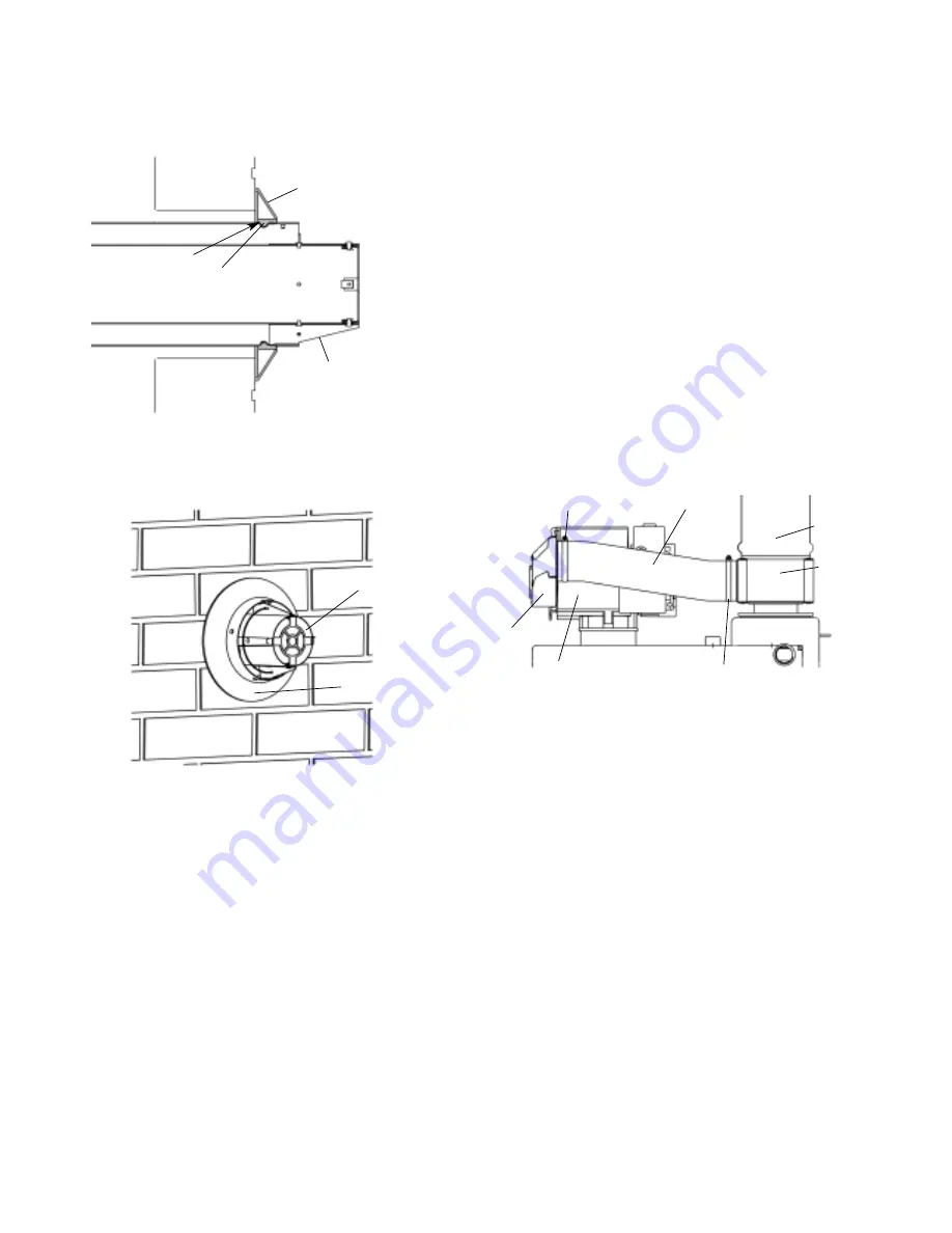
Fig. 6a. Fitting of rubber sealing gasket
Rubber sealing
gasket
Rubber sealing
gasket
Flue terminal
Locating slot
A
Flue terminal
Fig. 6b. Fitting of rubber sealing gasket
Fig. 7. Connection of the flexible air hose to the burner and air box
Locking band
Burner
aircowl
Burner
Locking band
Flexible duct
Flue
section
Airbox
5
4.3. Left and Right Side Discharge Low Level
Flues as shown in figure 2a
Using the
Standard
RS flue kit
If L is between :
145 – 315mm – (no extensions)
645 – 815mm – (500mm extension)
1145 – 1315mm – (1000mm extension)
1645 – 1815mm – (1000mm and 500mm extensions)
2145 – 2315mm – (2 x 1000mm extensions)
Using the
Long
RS flue kit
If L is between:
315 – 645mm – (no extensions)
815 – 1145mm – (500mm extension)
1315 – 1645mm – (1000mm extension)
1815 – 2145mm – (1000mm and 500mm extensions)
2315 –2500mm – (2 x 1000mm extensions)
4.4. Left and Right Side Discharge High Level
Horizontal flue with one 90° Bend as shown in
figure 2b
.
L is calculated by taking the dimension from Section
4.3 for left and right side Discharge Low Level Flues
and subtracting the vertical extension length L1
5. Siting of the Flue Terminal
5.1.
The flue terminal must be located in a suitable
position, such that the products of combustion can
be freely dispersed without the possibility of the
gases entering the dwelling or that of a neighbouring
dwelling.
5.2.
Discharge of flue gases into carports or narrow
passageways is not recommended.
5.3.
The terminal must not cause an obstruction or
the discharge cause a nuisance as a result of either
flue gases or terminal noise.
5.4.
Where the flue terminal is fitted less than 2
metres above the surface to which people have
access, fit a terminal guard. A suitable terminal guard
is available from Worcester Heat Systems, Part
Number 7 716 190 009, or alternatively a propriety
terminal guard may be used provided it leaves at
least 50mm clearance between the terminal and ter-
minal guard as shown in Fig. 3.
5.5.
If the terminal is fitted within 1 metre of a plastic
or painted gutter or within 500mm of painted eaves
then an aluminium or stainless steel shield at least 1
metre long should be fitted to protect the surface.
5.6.
Take care to ensure the combustion products do
not enter ventilated roof voids.
6. Installation
6.1.
The method of installation will depend on the flue
system layout, any installation restrictions and the
preferred method chosen by the installer.
In all installation methods the basic assembly princi-
ple remains the same. The various flue sections push
fit together until the flue hits the backstop in the pre-
vious flue. The flue/air seals must be coated with the
silicon grease supplied, to allow easy assembly. Take
care to avoid contaminating the grease with dirt as
this will make fitting difficult!
Each flue section must be securely fastened together
by drilling through the two pilot holes in each sec-
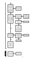
Fig. 3. Flue Terminal Guard
Fig. 4. Air Box Assembly
Flue section
(elbow or extension kit)
Fixing screws
(No 6 self tapers)
Self tapping screw
50mm
minimum
50mm
minimum
50mm
minimum
Flue terminal
Flue terminal
guard
Fixing hole
Collar
Flue tube
Flue tube retainer
Flue ring gasket
Flue outlet plate
Air box
Air tube
4
Содержание RD 628
Страница 34: ...34 1 2 3 4 7 5 6 8 9 10 11 12 4 15 13 16 19 14 17 18 20 22 23 21 ...
Страница 45: ...45 ...
Страница 46: ...46 ...
Страница 47: ...47 ...
Страница 51: ......
Страница 53: ......
Страница 55: ...L2 0mm ...
Страница 57: ......
Страница 58: ...RD 628 USER INSTRUCTIONS CUSTOMER CARE GUIDE G C NUMBER 47 108 14 ...
Страница 71: ...14 ...