background image

Page 27

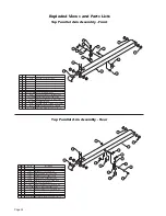
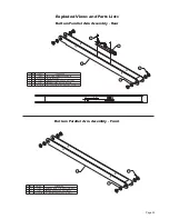
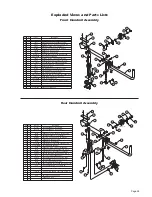
Exploded Views and Parts Lists

Vertical Arm Assembly - Rear

Vertical Arm Assembly - Front

945-5353

1000-2395A

37968

954-0454FNWBM

4

1

2

1
1

1

6
5

1
1

ROLLER-ASSY-ARM-TORQUE SHAFT

LIGHT ASSY-LED PLATFORM LIGHT
WMT-VERTICAL CHANNEL-FRONT-54"

RETAINER-LIFT TITE ROLLER

PART NO.

QTY.

ITEM

DESCRIPTION

81064-000

SCREW-1/4-20 X BHCS SS

7

1

32408

RUBBER BUMPER-VERT CHAN.

8

3

936-0403

PIN-PIVOT PARALLEL ARM

9

3

25346

WASHER-1/2" FLAT/AUTO-BK

10

3

25527

SCREW-5/16-18 X 3/4" FHS/AUTO-BK

945-5353

1000-2395A

37968

954-0454RNWBM

4

1

2

1
1

1

7

5

1

1

ROLLER ASSY-ARM-TORQUE SHAFT

LIGHT ASSY-LED PLATFORM LIGHT
WMT-VERTICAL CHANNEL-REAR-54"

RETAINER-LIFT TITE ROLLER

32408

RUBBER BUMPER-VERT CHAN.

8

1

9

2

33689A

ASSY-BRIDGE SWITCH W/ HARN/NL/NCL-2

37049

SCREW-#4-40 X 3/8" THREAD FORM

10

11

12

3

936-0403

PIN-PIVOT PARALLEL ARM

3

25346

WASHER-1/2" FLAT/AUTO-BK

3

25527

SCREW-5/16-18 X 3/4" FHS/AUTO-BK

13

1

15886BK

COTTER PIN-1/4" X 2"/AUTO-BK

81064-000

PART NO.

QTY.

ITEM

DESCRIPTION

6

1

SCREW-1/4-20 X 1" BHCS SS

3

3

DWG. NOTES

1) INSERT SOCKET OF LIGHT ASSY THRU TOP KEY

    WHILE INSTALLING LIGHT. TIGHTEN SCREWS.

2) HARNESS TO BE TUCKED INSIDE CHANNEL.

3) APPLY LOCTITE

®

 THREADLOCKER BLUE 242

®

    OR  EQUIVALENT  

4) APPLY LOCTITE

®

 THREADLOCKER RED 271™

    OR EQUIVALENT TO ALL #25527 SCREWS.

8

NOTE:

2

9

NOTE:

4

4

5

1

6

12

11

NOTE:

3

10

3

3

10

10

7

12

11

12

11

3

3

1

7

5

4

8

8

8

3

6

NOTE:

2

NOTE:

3

2

10

9

10

3

11

3

3

9

10

9

DWG. NOTES

1) INSERT SOCKET OF LIGHT ASSY THRU TOP KEY

    WHILE INSTALLING LIGHT. TIGHTEN SCREWS.

2) APPLY LOCTITE

®

 THREADLOCKER BLUE 242

®

 OR EQUIVALENT

3) APPLY LOCTITE

®

 THREADLOCKER RED 271™ OR EQUIVALENT TO ALL 

#25527 SCREWS.

"A"

DETAIL A

4

30063

RIVET-PUSH IN-8MM

4

30063

RIVET-PUSH IN-8MM

NOTE:

1

NOTE:

1

2

13

11

1

COTTER PIN-1/4" X 2"/AUTO-BK

15886BK

945-5353

1000-2395A

37968

954-0454FNWBM

4

1

2

1
1

1

6
5

1
1

ROLLER-ASSY-ARM-TORQUE SHAFT

LIGHT ASSY-LED PLATFORM LIGHT
WMT-VERTICAL CHANNEL-FRONT-54"

RETAINER-LIFT TITE ROLLER

PART NO.

QTY.

ITEM

DESCRIPTION

81064-000

SCREW-1/4-20 X BHCS SS

7

1

32408

RUBBER BUMPER-VERT CHAN.

8

3

936-0403

PIN-PIVOT PARALLEL ARM

9

3

25346

WASHER-1/2" FLAT/AUTO-BK

10

3

25527

SCREW-5/16-18 X 3/4" FHS/AUTO-BK

945-5353

1000-2395A

37968

954-0454RNWBM

4

1

2

1
1

1

7

5

1

1

ROLLER ASSY-ARM-TORQUE SHAFT

LIGHT ASSY-LED PLATFORM LIGHT
WMT-VERTICAL CHANNEL-REAR-54"

RETAINER-LIFT TITE ROLLER

32408

RUBBER BUMPER-VERT CHAN.

8

1

9

2

33689A

ASSY-BRIDGE SWITCH W/ HARN/NL/NCL-2

37049

SCREW-#4-40 X 3/8" THREAD FORM

10

11

12

3

936-0403

PIN-PIVOT PARALLEL ARM

3

25346

WASHER-1/2" FLAT/AUTO-BK

3

25527

SCREW-5/16-18 X 3/4" FHS/AUTO-BK

13

1

15886BK

COTTER PIN-1/4" X 2"/AUTO-BK

81064-000

PART NO.

QTY.

ITEM

DESCRIPTION

6

1

SCREW-1/4-20 X 1" BHCS SS

3

3

DWG. NOTES

1) INSERT SOCKET OF LIGHT ASSY THRU TOP KEY

    WHILE INSTALLING LIGHT. TIGHTEN SCREWS.

2) HARNESS TO BE TUCKED INSIDE CHANNEL.

3) APPLY LOCTITE

®

 THREADLOCKER BLUE 242

®

    OR  EQUIVALENT  

4) APPLY LOCTITE

®

 THREADLOCKER RED 271™

    OR EQUIVALENT TO ALL #25527 SCREWS.

8

NOTE:

2

9

NOTE:

4

4

5

1

6

12

11

NOTE:

3

10

3

3

10

10

7

12

11

12

11

3

3

1

7

5

4

8

8

8

3

6

NOTE:

2

NOTE:

3

2

10

9

10

3

11

3

3

9

10

9

DWG. NOTES

1) INSERT SOCKET OF LIGHT ASSY THRU TOP KEY

    WHILE INSTALLING LIGHT. TIGHTEN SCREWS.

2) APPLY LOCTITE

®

 THREADLOCKER BLUE 242

®

 OR EQUIVALENT

3) APPLY LOCTITE

®

 THREADLOCKER RED 271™ OR EQUIVALENT TO ALL 

#25527 SCREWS.

"A"

DETAIL A

4

30063

RIVET-PUSH IN-8MM

4

30063

RIVET-PUSH IN-8MM

NOTE:

1

NOTE:

1

2

13

11

1

COTTER PIN-1/4" X 2"/AUTO-BK

15886BK

Содержание Century 2 NCL954

Страница 1: ...her than motor homes with a gross vehicle weight rating GVWR that exceeds 4 536 kg 10 000 lb DOT Public Use Lift NCL954 Series GA and Serial Numbers 1412300001 to 15040700056 and Rev A Century 2 401338 Rev B August 2015 WARNING Read manual before installing or servicing lift Failure to do so may result in serious bodily injury and or property damage ual Man 631 West 11th Street P O Box 310 Winamac...

Страница 2: ... No Model No Two BraunAbility Serial No identification tags shown below are posted on the lift One I D tag is posted on the opposite pump side vertical arm A second I D tag is located on the opposite pump side tower Both I D tags provide the product identification information provided on the warranty registration card Record the information in the space provided or document on a copy This informat...

Страница 3: ...hematic 15 Lift Wiring Diagram 16 Hydraulics Hydraulic Schematic 17 Hydraulics Parts List 18 Hydraulics Diagram 19 Repair Parts Pump Module Pump Module Parts List 20 Pump Module Diagram 21 Lift Exploded Views and Parts Lists NCL954IB3454 2 Base Plate Assembly 22 NCL954FIB3454 2 Base Plate Assembly 23 Top Parallel Arm Assembly 24 Bottom Parallel Arm Assembly 25 Hydraulic Cylinder Assembly Main 26 V...

Страница 4: ...al Arm Bottom Parallel Arms 2 Platform Lights 2 Rear Front Outboard passenger s side Inboard driver s side of vehicle of vehicle Outboard Right Front Lift Tite Latches 2 Unfold Assist Compression Springs 2 Outer Barrier Activation Foot Outer Barrier Latches 2 Platform Side Plates 2 Platform Left Rear Inboard Towers 2 Threshold Warning Plate Audible Threshold Warning not visible Visual Threshold Wa...

Страница 5: ...IB Occupied Stow Interlock Assy 32514NA 54 Unfold Microswitch Threshold Alarm Microswitch Up Unfold Microswitch Assy 975 4121A Threshold Alarm Partial Fold Microswitch Assy 975 4121A IB Raised Switch 32519KS Partial Fold Microswitch Outer Barrier Occupied Raised Microswitch Rear 33775A Note Mirror image for right front pump lifts Bridging Microswitch 33689KS Outer Barrier Occupied Raised Microswit...

Страница 6: ...ressure Adjustment procedures The inner roll stop will not raise if occupied Call BraunAbility Aftersales The outer barrier will not raise if occupied Refer to Outer Barrier Fold Pressure Adjustment procedures Verify platform lighting when lift is deployed and pendant illumination when lift is powered 1 Replace bulb s in the light housing A warning will activate if the threshold area is occupied w...

Страница 7: ...button until the plat form folds completely Note Return the platform to floor level position after each attempt to fold the platform 5 Turn the adjustment screw an additional 1 8 turn after the platform folds successfully 6 Tighten the hex nut without moving the adjustment screw 7 Verify the platform will not stow while occupied Platform Fold Pressure Adjustment Platform Fold Adjustment Allen Scre...

Страница 8: ...ning as detailed in Tower Microswitch Adjustment Stop Block Vertical Arm Adjustment Screw Stop blocks must make full contact 1 The outboard end toe of the platform must contact the ground first to ensure the spring loaded outer barrier unfolds fully See Figure A 2 The inboard end heel of the platform must lower fully vertical arms must contact ground when fully lowered See Figure A The angle of th...

Страница 9: ...cal arms C D Stop Block Guideline All Lift Models Right Wrong Turn clockwise to raise outboard end of platform When adjusting platform angle setting floor level position or adjusting bridging microswitch ensure both stop blocks are making full contact with the vertical arms Stop Block Vertical Arm Stop Block Vertical Arm Turn counter clockwise to lower outboard end of platform To raise the outboar...

Страница 10: ...ower 1 Unfold Switch Adjustment Floor Position from Stow 1 Position platform at the fully stowed position using the manual hand pump or pendant control 2 Turn switch adjustment screw clock wise 3 full turns 3 Press pendant UNFOLD switch con tinue pressing switch until platform stops unfolding 4 When platform stops unfolding turn switch adjustment screw coun terclockwise while pressing the pendant ...

Страница 11: ...Page 9 NOTES This page intentionally left blank ...

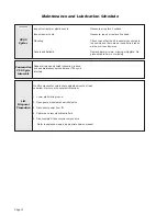
Страница 12: ...ter Barrier Latch Roller Bearing 2 LO Outer Fold Arm Cam Followers 4 LO Inner Fold Arm Roller Pin Bearings 4 LO Hydraulic Cylinder Pivot Bushings 8 LO Inner Roll Stop Lever Bearings 2 and Slots 2 LO Outer Barrier Switch Lever Pivot Points 2 LO See the Maintenance Lubrication Schedule for recommended applications per number of cycles Outer Barrier Activation Foot Bearings 4 LO Inner Outer Fold Arm ...

Страница 13: ...nance procedures should be repeated at 750 cycle intervals fol lowing the scheduled 4500 cycle maintenance procedures These intervals are a general guideline for scheduling maintenance procedures and will vary according to lift use and conditions Lifts exposed to severe con ditions weather environment contamination heavy usage etc may require inspection and maintenance procedures to be performed m...

Страница 14: ...Inner roll stop lever bearings 2 Inner roll stop lever slot 2 Saddle support bearings 8 Outer fold arm roller pin bearings 4 Outer fold arm cam followers 4 Parallel arm pivot pin bearings 16 Handrail pivot pin bearings 4 Hydraulic cylinder pivot bushings 8 Inspect Lift Tite latch rollers for wear or damage positive securement and proper operation 2 Inspect inner roll stop for Wear or damage Proper...

Страница 15: ...er barrier latch pivots 2 Outer barrier switch lever pivot 2 Outer barrier latch rollers 2 Outer fold arm cam followers 4 Outer fold arm roller pins 4 Inner roll stop lever bracket pins 2 Inspect inner fold arm pins 2 axles 2 and bearings 8 for wear or damage and positive securement Remove pump module cover and inspect Hydraulic hoses fittings and connections for wear or leaks Harness cables wires...

Страница 16: ...d to the vehicle and there are no loose bolts broken welds or stress fractures Replace decals if worn missing or illegible Re place antiskid if worn or missing Maintenance and Lubrication Schedule continued Lift Disposal Procedure No lift components contain unacceptable amounts of lead cadmium mercury or hexavalent chromium 1 Lower platform to ground 2 Open pump module manual relief valve 3 Discon...

Страница 17: ... 20 GN 20 WH 20 RD 18 WH 18 BK 18 BK 18 WH 18 WH 18 DK BU 18 WH 18 LT BU GN 18 GN 18 GN 20 WH 18 WH 18 BK 18 RD 18 OR 12 OR 12 OR 12 OR 12 OR 12 RD 18 RD 18 BK 18 GN 18 GN 18 GN 18 RD 18 BK 20 BK 18 BK 18 BK 20 GN 14 GN 20 GN 20 BK 22 RD 22 BK 20 BK 20 BU 20 BU 20 BN 20 WH 18 BN 20 GN 20 BK 18 BK 18 BU 20 RD 10 CIRCUIT BREAKER GN 14 YL 14 BK 4 RD 10 RD 10 BK 20 RD 2 RD 4 RD 4 RD 4 GN 20 GN 20 GN 2...

Страница 18: ...ady LED RD 18 RD 18 RD 18 RD 18 RD 18 RD 18 RD 18 RD 18 RD 18 RD 18 RD 18 OR 12 OR 12 OR 12 OR 12 Light Relay 85 87a 86 87 30 BK 18 BK 18 RD 18 RD 18 WH 18 BK 18 FOLD RELAY 85 87a 86 87 30 GN 18 LT BU GN 18 4 3 2 1 COLOR NO 4 COND WIRE CODE NOT USED RED 18 WHITE 18 BLACK 18 3 4 1 2 4 3 2 1 COLOR NO 4 COND WIRE CODE NOT USED WHITE 18 BLUE 18 BLACK 18 2 1 4 3 2 1 5 3 6 4 ORANGE 18 WHITE 18 RED 18 BL...

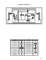
Страница 19: ...or Hydraulic Port M Orifice 1200 PSI Secondary Valve Folding Relief Valve Lifting Relief Valve Orifice Pump Side Cylinder BACKUP PUMP 2500 PSI Down Valve 1900 PSI PUMP Opposite Pump Cylinder Fixed Displacement Pump Vented Reservoir Backup Pump Single Acting Cylinder Check Valve Manual Shutoff Valve 2 Way 2 Position Solenoid Valve Pressure Compensated Flow Control Relief Valve Description Symbol De...

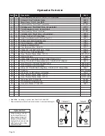
Страница 20: ...th Grip 17206A 19 1 Fitting Male 7 16 20 SAE O Ring to Male 7 16 20 JIC 37 24504 20 1 Elbow 7 16 20 JIC 37 Female Swivel 1 7 16 20 JIC 37 Male 2 26579 21 1 Hose Assembly 1 8 Opposite Pump Side 16004A 090 22 1 Hose Assembly 1 8 Pump Side 16004A 051 23 2 Elbow 90 7 16 20 SAE O Ring Male 7 16 20 JIC 37 Male Orifice 26667 24 2 Cylinder C1516 5 0409BM 25 2 Elbow 90 1 4 NPT Male to 1 4 Barbed 15150 26 1...

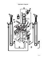
Страница 21: ...ackup Pump 21 22 18 9 12 24 20 19 27 30 16 13 3 10 26 25 Hydraulic Pump Motor Pump Side Cylinder 14 17 15 25 23 23 11 1 29 Hydraulic Repair For repair of a hydraulic hose or cylinder read this Service Bulletin 27049 2 28 7 4 Hydraulics Diagram ...

Страница 22: ...rness Main 945 2500NA 945 2500NA 35 1 Fitting Male 7 16 20 O Ring to Male 7 16 20 JIC 37 24504 24504 36 1 Cable Lift Chassis Ground 22166A 22166A 37 1 Wire Assembly Lift Interlock Connection 31797A 31797A 38 1 Wire Assembly Lift Stowed Connection 3See note below 31798A 31798A 39 1 Rubber Boot Red 3See note below 82046 82046 40 1 Control Hand Pendant Assembly Non Electronic Non Shielded Coiled 3See...

Страница 23: ...22 6 16 6 14 25 24 3 18 1 24 16 UP DO WN 32819 FOL D UN FOL D 32820 32 20 2 Pump Mounting Bolts Apply Loctite Threadlocker Red 271 or equivalant to the three pump mount ing bolts items 25 and 26 if a blue nylon patch is not present on the bolts when retrofitting an M268 pump as sembly Note Rear pump module shown front pump module mirror image ...

Страница 24: ...AP ZINC PLATED BOLT 3 8 16 X 1 2 W NYLOCK PATCH BOLT SHOULDER 5 16 X 5 8 1 4 20 SS W PC DETAIL A SCALE 4X A NOTE NOTE 19 18 2 2 2 CLAMP INSULATED 1 3 8 29765 RIV POP SD66BS 3 16 25 38 AUTO BK 14993 WASHER 10 FLAT AUTO BK 11541 2 WASHER 5 16 FLAT 10063 1 6 9 3 4 5 10 13 7 11 15 8 18 14 19 12 21 DESCRIPTION PART NO ITEM QTY 1 4 4 4 PIN PIVOT PARALLEL ARM KIT THRESHOLD TRANSITION RUBBER NOSE WASHER 1...

Страница 25: ... 1 16 NUT 3 8 16 TOP LOCK AUTO BK WASHER 1 2 NYLON RING 5 16 EXT SNAP ZINC PLATED BOLT 3 8 16 X 1 2 W NYLOCK PATCH BOLT SHOULDER 5 16 X 5 8 1 4 20 SS W PC DETAIL A SCALE 4X NOTE NOTE 19 18 2 2 2 CLAMP INSULATED 1 3 8 29765 RIV POP SD66BS 3 16 25 38 AUTO BK 14993 WASHER 10 FLAT AUTO BK 11541 2 WASHER 5 16 FLAT 10063 1 6 9 3 4 5 10 13 7 8 18 14 19 15 12 11 21 A DESCRIPTION PART NO ITEM QTY 1 4 4 4 P...

Страница 26: ...5 16 18 X 3 4 AUTO BK 13 1 10068 WASHER 5 16 LOCK AUTO BK 14 1 30996BK NUT 5 16 18 ACORN 15 1 10062 NUT 5 16 18 HEX AUTO BK 1 10 7 11 14 13 15 8 9 6 12 2 1 6 12 4 5 3 7 8 9 10 11 15 13 14 2 4 5 3 1 24011 4 2 1 1 954 0419FNA BEARING FLANGE 3 4 X 3 8 12FDU06 ASSY PARALLELARM TOP 54 FTG Incl Items 1 15 3 4 34398 WASHER 0 906 ID X 1 25 OD X 075 TH ZINC 4 5 1 945 0450BM CAP PARALLEL ARM 2 11513 RIV POP...

Страница 27: ...EM PART NO 954 0412NA 1 2 BEARING FLANGE 3 4 X 3 8 12FDU06 4 24011 WASHER 0 906 ID X 1 25 OD X 075 TH ZINC 3 34398 4 1 2 3 5 4 WASHER 0 906 ID X 1 25 OD X 075 TH ZINC 34398 4 ASSY ARM PARALLEL BOTTOM PUMP Incl Items 1 5 BEARING FLANGE 3 4 X 3 8 12FDU06 ASSY IB OCCUPIED 4 3 2 1 32514NA 54 1 954 0458NA 24011 4 1 ITEM PART NO QTY DESCRIPTION NUT 10 32 W LOCKWASHER AUTO BK 5 18349 2 ...

Страница 28: ...ic Cylinder Assembly Main 1 3 2 RETRACTED EXTENDED STROKE 16 499 48 716 32 217 CYLINDER 16 499 32 217 RETRACTED ELBOW 1 4 NPT 90 1 4 BARB ELBOW 7 16 20 M O RNG 37 035 ORFICE 15150 26667 C1516 5 0409BM 3 2 1 1 1 1 DESCRIPTION PART NO ITEM QTY 30 10 ...

Страница 29: ...ALENT TO ALL 25527 SCREWS A DETAIL A 4 30063 RIVET PUSH IN 8MM 4 30063 RIVET PUSH IN 8MM NOTE 1 NOTE 1 2 13 11 1 COTTER PIN 1 4 X 2 AUTO BK 15886BK 945 5353 1000 2395A 37968 954 0454FNWBM 4 1 2 1 1 1 6 5 1 1 ROLLER ASSY ARM TORQUE SHAFT LIGHT ASSY LED PLATFORM LIGHT WMT VERTICAL CHANNEL FRONT 54 RETAINER LIFT TITE ROLLER PART NO QTY ITEM DESCRIPTION 81064 000 SCREW 1 4 20 X BHCS SS 7 1 32408 RUBBE...

Страница 30: ... 1 SMOOTH SIDE 2 DESCRIPTION PART NO QTY ITEM 1 2 954 0704NA DESCRIPTION PART NO QTY ITEM COVER PLASTIC PARALLEL ARM OUTSIDE FRONT SMOOTH SIDE 3 1 1 954 0701NA COVER PLASTIC PARALLEL ARM INSIDE FRONT COVER PLASTIC PARALLEL ARM INSIDE REAR 954 0703NA 4 1 COVER PLASTIC PARALLEL ARM OUTSIDE REAR 954 0702NA 3 1 SMOOTH SIDE 4 SMOOTH SIDE 1 SMOOTH SIDE 2 DESCRIPTION PART NO QTY ITEM 1 2 954 0704NA DESCR...

Страница 31: ...D X 750 OD X 025 AUTO BK 25336 1 24 BEARING FLANGE 1 2 X 1 4 08FDU04 24442 1 23 LEVER INBOARD BARRIER 954 0404NBM 1 18 DETAIL A 18 A 25 24 4 14 6 8 10 11 1 3 4 9 5 6 5 4 3 1 QTY ITEM PART NO DESCRIPTION 11 10 8 9 14 16 17 19 20 21 15 1 1 2 1 2 1 1 1 10027 BOLT 3 8 16 X 2 HEX HD CAP 18657 RING 3 4 EXT SNAP AUTO BK 900 0413N PIN PIVOT LOWER ARM INCLUDES 1 ITEM 4 915 2606NBM SLIDE PLATFORM ROTATE 954...

Страница 32: ... 1 2 2 32 30236R048 5 DECAL BOUNDARY YELLOW LEXAN 1 x 32 1 2 1 33 30236R032 5 HAIRPIN COTTER STAINLESS 042 2 34 36003 PART NO QTY ITEM DESCRIPTION ITEMS NOT SHOWN DECAL BOUNDARY YELLOW LEXAN 1 X 11 2 35 30236R011 BOLT 3 8 16 x 3 4 FLBHSCS GD8 4 36 25171 BEARING FLANGE 3 4 X 1 4 12FDU04 2 37 24012 NUT 1 4 20 NYLOCK ZINC 2 38 14614Z BUMPER SWITCH 1 40 38660 NUT 3 8 16 HEX AUTO BK 4 41 10059BK BUMPER...

Страница 33: ...ound to exist during the fourth or fifth year of warranty coverage to the following lift s power train parts Cable Cylinder Flow Control Gear Box Motor Pump Hydraulic Hose and Fittings it will be repaired or replaced at Braun s option without charge to the owner for parts only in accordance with the terms conditions and limitations of this limited warranty The cost of labor for repair or replaceme...

Страница 34: ...tted by law notify Braun directly in writing at the above address of the unsuccessful repair s of the alleged defect s so that Braun can become directly involved in providing service pursuant to the terms of this limited warranty WHAT IS NOT COVERED This Limited Warranty does not cover any of the following defects in materials components or parts of the product not attributable to Braun any materi...

Страница 35: ...any action of Braun or any agent of Braun shall be interpreted as an extension of any warranty period or the filing limitation period in this paragraph Some states do not allow a reduction in the statute of limitations so this reduction may not apply to you WARRANTY REGISTRATION and MISCELLANEOUS Your warranty registration records should be completed and delivered to the appropriate companies incl...

Страница 36: ...56 and Rev A Century 2 Service Manual All illustrations descriptions and specifications in this manual are based on the latest product information available at the time of publication The Braun Corporation reserves the right to make changes at any time without notice 401338 Rev B August 2015 631 West 11th Street P O Box 310 Winamac IN 46996 USA Phone 1 574 946 4139 1 800 THE LIFT www braunability ...

Отзывы: