3. Installation
1
3
2
5
4
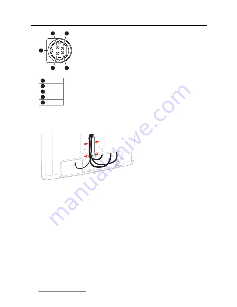
Image 3-9
1
GND
2
+V
3
GND
4
+V
5
Earth
3.2.5
Step 5: Cable routing
To route the cables
1. Route all connected cables through the cable routing channel.
Image 3-10
3.2.6
Step 6: Cover reattachment
For displays to be mounted on the stand/handle or on a VESA arm with internal
cable routing provisions
1. Slide the connector compartment cover upwards so that it
fi
ts onto the display.
2. Reattach the connector compartment cover by tightening the
fi
xation screw.
12
(451920611082)K5902070 MSMD-1119 & MSMD-1119-TS 05/12/2013


