5
GB
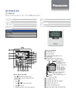
INDICATIONS AND CONTROLS
(see fig. 1)
1
Sensor push button for cover
closing.
2 R
Reset.
3
Button for viewing the
programmed temperature and
temperature threshold.
4
Push button for clock setting
and for on-off time delays.
5
Button for selecting the cooling
(
) or heating program (
).
6
Digital clock.
7
Battery charge status.
8 OFF
Stand-by mode indicator.
9
Display of on-off time delays.
10
MANUAL mode indicator.
P
11
Cooling program indicator.
12
Heating program indicator.
13
Digital thermometer.
14
Button for selecting MANUAL
or AUTOMATIC thermostat
mode.
15
Knob for manual temperature
adjustment.
When the knob is turned, the
temperature field of the
display shows the set tempe-
rature for 4 s.
16
When this warning appears, it
means the batteries are low
.
17
Button for disabling ther-
mostat control, either with or
without anti-freeze protection.
18
Push button for activation
TIMED MANUAL PROGRAM
or STAND-BY MODE.
19
Increase (temperature, day,
time, etc.).
20
Decrease (temperature, day,
time, etc.).
21 6÷24°C
Temperature range for heating
(
) program in MANUAL
operation.
22 18÷31°C Temperature range for cooling
(
) program in MANUAL
operation. A position which
exceeds 31 °C (O) places the
system in OFF status.
23
Cursors for temperature
setting in AUTOMATIC mode
for each hour of the day.
When the cursor is moved, in
the hours field the hour that
corresponds to the cursor is
displayed, while the
temperature field shows the
set temperature for 4 s.
24 6÷24°C
Temperature range for heating
program (
).
0
÷
23
TH125_ITF 24081800 01_07 15-01-2007 16:23 Pagina 5


