250 Outrage
Section 4 • Electrical System
DC Electrical System
The DC electrical system on the 250 Outrage is
powered by two (2) lead-acid batteries. The batteries
are charged by the engines when the engines are
running or by shore power when connected. The
batteries power essential systems on your boat:
• Engine Ignition.
• Engine tilt trim system
• Helm switch panel & helm instrument
panel
• Navigation Lighting system
• Livewell system
• Electronics and add-on accessories
• Lighting
Batteries
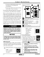
The Battery Trays located forward in the console
interior house and secure the batteries (Figure
4.1.1). The batteries can be installed or removed by
NOTICE
Always store the batteries in the battery trays.
Use the retaining lid and wingnuts to keep the
batteries secure while underway.
Battery Trays
1
CONSOLE INTERIOR
STARBOARD (SINGLE ENGINE) BATTERY
HOUSE BATTERY
HOUSE MAIN BREAKER
PORT ENGINE BATTERY (OPTION)
VSR (VOLTAGE SENSITIVE RELAY)
2
3
4
Battery Trays
Fig.4.1.1
FWD
Application
Group Volts MCA*
RC 25
Qty.
USA (SAE)
31
12
800
135 min
2**
* Marine Cranking Amps
NOTICE
REFER TO YOUR ENGINE OWNER’S MANUAL FOR
EXACT BATTERY REQUIREMENTS.
The chart below is provided for reference purposes
only.
Use only AGM batteries with Verado
engines.
Application
Group Volts
CCA*
Reserve
Qty.
Intn’l (EN)
31
12
975
65Ah
2**
* Cold Cranking Amps
loosening the wing nuts and removing the retaining
lid on the battery tray.
Battery Care
Your batteries should always be enclosed in the
battery trays provided with your boat and secured
in place by the retaining lids. The trays will ensure
that while underway the batteries will not move
around, thus causing damage to components fi tted
in the same area.
Before use, check each battery and the charging
system for loose connections or wiring. Normal
maintenance should include:
• Coating the terminals with dielectric grease
• Keeping the batteries dry
** Dual engine option requires a third battery
** Dual engine option requires a third battery
1
2
3
5
4
6
5
6
NOTICE
Ensure that your batteries meet Mercury’s AGM
& CCA requirements
Battery Trays (Dual Engine Option)
If your boat is equipped with the dual engine option
a third battery will be located in the forward section
of the console interior. The additional battery powers
the port engine.
Содержание 250 OUTRAGE
Страница 1: ...i R 250 Outrage 250 Outrage ...
Страница 2: ...ii R ...
Страница 18: ...xviii î ï ð ñ ò ó ô õ ö R ø ù ú û ü ý þ ÿ ú ø ÿ ø ú ý ÿ ø ý ...
Страница 42: ...1 24 Ë Ì Í Î Ï Ð Ñ Ò Ó Ô R Õ Ö Ø Ù Ú Û Ü Ý Õ Ü Ý Õ Þ Ý Ú ß ß à ß Ü á Õ â ß Ú Ý ã ...
Страница 54: ...2 12 w x y z R ª ª ª ª ª ª ª ª ª µ ª º ª º µ ...
Страница 72: ...2 30 µ R º À À Á À Â Ã À Ä ...
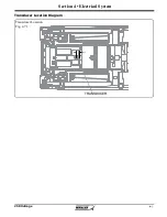
Страница 109: ...250 Outrage Section 4 Electrical System Transducer Location Diagram Transducer Location Fig 4 7 1 TRANSDUCER ...
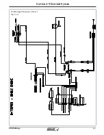
Страница 111: ...250 Outrage Section 4 Electrical System 250 Outrage Schematic Sheet 1 Fig 4 9 1 ...
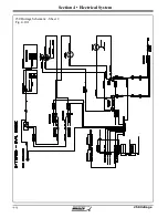
Страница 112: ...250 Outrage Section 4 Electrical System 250 Outrage Schematic Sheet 2 Fig 4 10 1 ...
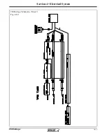
Страница 113: ...250 Outrage Section 4 Electrical System 250 Outrage Schematic Sheet 3 Fig 4 11 1 ...
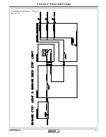
Страница 114: ...250 Outrage Section 4 Electrical System 250 Outrage Schematic Sheet 4 Fig 4 12 1 ...
Страница 115: ...250 Outrage Section 4 Electrical System 250 Outrage Schematic Sheet 5 Fig 4 13 1 ...
Страница 116: ...250 Outrage Section 4 Electrical System 250 Outrage Schematic Sheet 6 Fig 4 14 1 ...
Страница 117: ...250 Outrage Section 4 Electrical System 250 Outrage Schematic Sheet 7 Fig 4 15 1 ...
Страница 118: ...250 Outrage Section 4 Electrical System 250 Outrage Schematic Sheet 8 Fig 4 16 1 ...
Страница 119: ...250 Outrage Section 4 Electrical System 250 Outrage Schematic Sheet 9 Fig 4 17 1 ...
Страница 120: ...250 Outrage Section 4 Electrical System 250 Outrage Schematic Sheet 10 Fig 4 18 1 ...
Страница 121: ...250 Outrage Section 4 Electrical System 250 Outrage Schematic Sheet 11 Fig 4 19 1 ...
Страница 122: ...250 Outrage Section 4 Electrical System 250 Outrage Schematic Sheet 12 Fig 4 20 1 ...
Страница 123: ...250 Outrage Section 4 Electrical System 250 Outrage Schematic Sheet 13 Fig 4 21 1 ...
Страница 124: ...250 Outrage Section 4 Electrical System 250 Outrage Schematic Sheet 14 Fig 4 22 1 ...
Страница 125: ...250 Outrage Section 4 Electrical System 250 Outrage Schematic Sheet 15 Fig 4 23 1 ...
Страница 126: ...250 Outrage Section 4 Electrical System 250 Outrage Schematic Sheet 16 Fig 4 24 1 ...
Страница 127: ...250 Outrage Section 4 Electrical System 250 Outrage Schematic Sheet 17 Fig 4 25 1 ...
Страница 128: ...250 Outrage Section 4 Electrical System 250 Outrage Schematic Sheet 18 Fig 4 26 1 ...
Страница 129: ...250 Outrage Section 4 Electrical System 250 Outrage Schematic Sheet 19 Fig 4 27 1 ...
Страница 130: ...250 Outrage Section 4 Electrical System 250 Outrage Schematic Sheet 20 Fig 4 28 1 ...
Страница 131: ...250 Outrage Section 4 Electrical System 250 Outrage Schematic Sheet 21 Fig 4 29 1 ...
Страница 132: ...250 Outrage Section 4 Electrical System THIS PAGE INTENTIONALLY LEFT BLANK ...
Страница 143: ...Section 5 Care Maintenance 250 Outrage Reinforcement Location Diagram ...

