250 Outrage
Section 4 • Electrical System
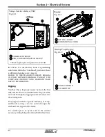
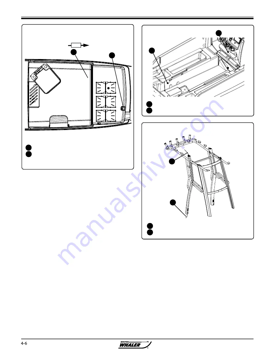
Rigging
Your boat has a large open space between the fuel
tank and the fl oor to run additional wiring. Feed the
new runs through the rigging boots and secure it to
the existing runs.
If equipped with the optional hardtop or T-top,
additional wiring. can be routed through the
starboard aft support of the frame.
Tie another piece of nylon cord to the current
accessory wiring being run and use that for later runs.
Rigging
Fig. 4.6.1
AFT PULL CORD
FORWARD PULL CORD
1
2
1
2
Hardtop/T-top Rigging
Fig. 4.6.2
FROM CONSOLE
TO HARDTOP
1
2
1
2
the chance of a dead battery bank if a paralleling
switch were le in the “Combined” position without
a suffi
cient charging source present.
REFER TO THE MANUFACTURER’S MANUAL
IN YOUR OWNER’S MANUAL PACKET FOR
COMPLETE INSTRUCTIONS, WARRANTY AND
SAFETY INFORMATION.
1
CONSOLE INTERIOR
VSR (VOLTAGE SENSITIVE RELAY)*
2
Voltage Sensitive Relays (VSR)
Fig.4.6.1
FWD
1
2
* Dual engine option requires two (2) VSR
Содержание 250 OUTRAGE
Страница 1: ...i R 250 Outrage 250 Outrage ...
Страница 2: ...ii R ...
Страница 18: ...xviii î ï ð ñ ò ó ô õ ö R ø ù ú û ü ý þ ÿ ú ø ÿ ø ú ý ÿ ø ý ...
Страница 42: ...1 24 Ë Ì Í Î Ï Ð Ñ Ò Ó Ô R Õ Ö Ø Ù Ú Û Ü Ý Õ Ü Ý Õ Þ Ý Ú ß ß à ß Ü á Õ â ß Ú Ý ã ...
Страница 54: ...2 12 w x y z R ª ª ª ª ª ª ª ª ª µ ª º ª º µ ...
Страница 72: ...2 30 µ R º À À Á À Â Ã À Ä ...
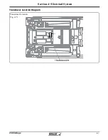
Страница 109: ...250 Outrage Section 4 Electrical System Transducer Location Diagram Transducer Location Fig 4 7 1 TRANSDUCER ...
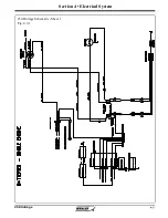
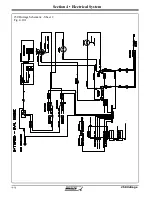
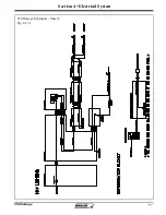
Страница 111: ...250 Outrage Section 4 Electrical System 250 Outrage Schematic Sheet 1 Fig 4 9 1 ...
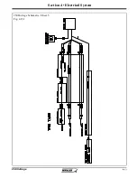
Страница 112: ...250 Outrage Section 4 Electrical System 250 Outrage Schematic Sheet 2 Fig 4 10 1 ...
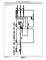
Страница 113: ...250 Outrage Section 4 Electrical System 250 Outrage Schematic Sheet 3 Fig 4 11 1 ...
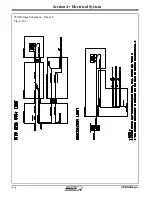
Страница 114: ...250 Outrage Section 4 Electrical System 250 Outrage Schematic Sheet 4 Fig 4 12 1 ...
Страница 115: ...250 Outrage Section 4 Electrical System 250 Outrage Schematic Sheet 5 Fig 4 13 1 ...
Страница 116: ...250 Outrage Section 4 Electrical System 250 Outrage Schematic Sheet 6 Fig 4 14 1 ...
Страница 117: ...250 Outrage Section 4 Electrical System 250 Outrage Schematic Sheet 7 Fig 4 15 1 ...
Страница 118: ...250 Outrage Section 4 Electrical System 250 Outrage Schematic Sheet 8 Fig 4 16 1 ...
Страница 119: ...250 Outrage Section 4 Electrical System 250 Outrage Schematic Sheet 9 Fig 4 17 1 ...
Страница 120: ...250 Outrage Section 4 Electrical System 250 Outrage Schematic Sheet 10 Fig 4 18 1 ...
Страница 121: ...250 Outrage Section 4 Electrical System 250 Outrage Schematic Sheet 11 Fig 4 19 1 ...
Страница 122: ...250 Outrage Section 4 Electrical System 250 Outrage Schematic Sheet 12 Fig 4 20 1 ...
Страница 123: ...250 Outrage Section 4 Electrical System 250 Outrage Schematic Sheet 13 Fig 4 21 1 ...
Страница 124: ...250 Outrage Section 4 Electrical System 250 Outrage Schematic Sheet 14 Fig 4 22 1 ...
Страница 125: ...250 Outrage Section 4 Electrical System 250 Outrage Schematic Sheet 15 Fig 4 23 1 ...
Страница 126: ...250 Outrage Section 4 Electrical System 250 Outrage Schematic Sheet 16 Fig 4 24 1 ...
Страница 127: ...250 Outrage Section 4 Electrical System 250 Outrage Schematic Sheet 17 Fig 4 25 1 ...
Страница 128: ...250 Outrage Section 4 Electrical System 250 Outrage Schematic Sheet 18 Fig 4 26 1 ...
Страница 129: ...250 Outrage Section 4 Electrical System 250 Outrage Schematic Sheet 19 Fig 4 27 1 ...
Страница 130: ...250 Outrage Section 4 Electrical System 250 Outrage Schematic Sheet 20 Fig 4 28 1 ...
Страница 131: ...250 Outrage Section 4 Electrical System 250 Outrage Schematic Sheet 21 Fig 4 29 1 ...
Страница 132: ...250 Outrage Section 4 Electrical System THIS PAGE INTENTIONALLY LEFT BLANK ...
Страница 143: ...Section 5 Care Maintenance 250 Outrage Reinforcement Location Diagram ...

