250 Outrage
Section 4 • Electrical System
Fuse Blocks
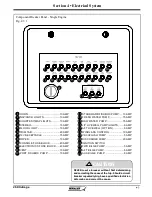
There is an electronics fuse block
located in the console which can
be accessed thru a panel on the aft
wall of the console interior and in
the port side of the optional hardtop
electronics box.
In the event you need to replace a fuse, use only the
same amperage as the original. It is recommended
that you carry spare fuses.
If a fuse is replaced with one of lower amperage, it
will not be suffi cient to carry the electrical load of the
equipment it is connected to and will cause nuisance
fuse failure or breaker tripping.
If a fuse is replaced with one of higher amperage,
it will not provide adequate protection against an
electrical malfunction and will create a fi re hazard.
Use of higher amperage fuses or breakers is a
fi re hazard.
Use fuses and breakers having the same amperage
rating as the original or as specifi ed.
WARNING
12 Volt Accessory Receptacle
Your 250 Outrage is equipped
with 12 volt accessory
receptacle in the lockable glove
box on the control console (See
fi g. 2.9.2). The DC receptacle
is to be used with any 12 volt
accessories using this style of
plug.
There is a 15 amp breaker located on the breaker
panel (labeled CTSY OUTLETS) panel (See fi gure
4.4.1).
Be sure to use accessories that do not exceed
the rated capacity of the circuit, (15 amps) or the
breaker will trip.
NOTICE
DO NOT insert a cigarette lighter into this
receptacle. Damage to the unit & system could
occur.
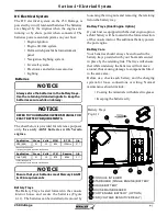
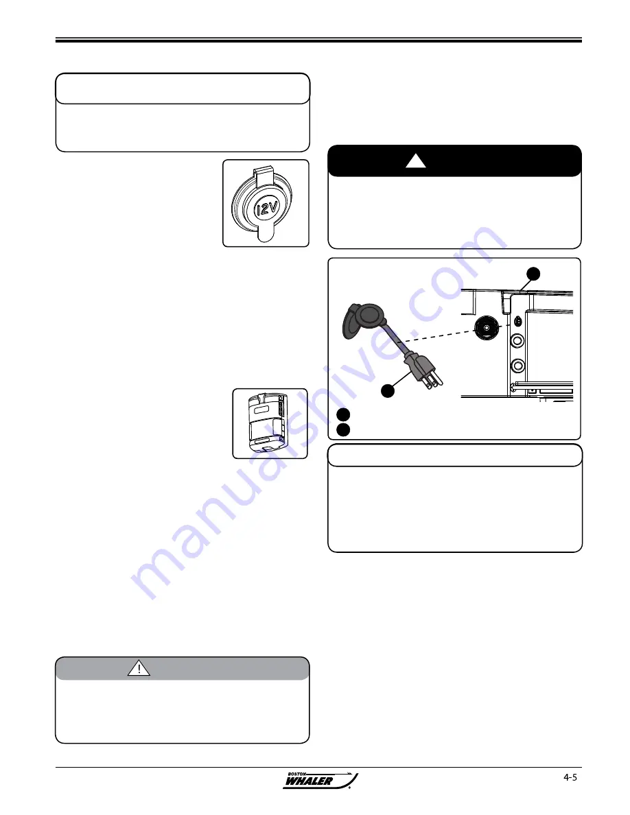
Dockside Battery Charging (Option)
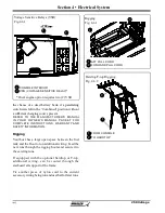
Your boat can be equipped with a battery charging
system which includes a battery charger and a short
extension cord located on the starboard side of the
deck which can be used to connect to an outlet to
charge the batteries.
Battery Charging system (Option)
Fig. 4.5.1
1
2
STARBOARD GUNWALE
RETRACTABLE EXTENSION CORD
AVOID serious injury or death from fi re
explosion or electrical shock.
!
DANGER
This device MUST be connected to a GFCI
(Ground Fault Circuit Interrupt) protected
outlet.
1
2
You can connect a heavy duty U.L. approved extension cord
to the charger. After connecting the extension cord to the
charger proceed to plug the extension cord to a nearby
120VAC GFCI (Ground Fault Circuit Interrupt) outlet.
ALWAYS remove the extension cord from the 120VAC outlet
fi rst when charging is completed, followed by unplugging
the charger.
NOTICE
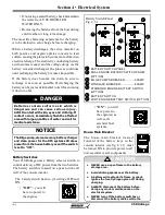
e battery banks on your boat are automatically
connected in parallel through the use of a VSR
(Voltage Sensitive Relay) located on the forward wall
of the console (Figure 4.6.1).
When a suffi
cient charging source is present.
e
battery banks are automatically separated when the
charging source falls below a certain voltage level for
a predetermined amount of time.
e use of VSRs eliminates the need for the operator
to monitor battery voltage and decide whether or not
it is ok to parallel the battery banks. It also eliminates
Voltage Sensitive Relays (VSR)
Содержание 250 OUTRAGE
Страница 1: ...i R 250 Outrage 250 Outrage ...
Страница 2: ...ii R ...
Страница 18: ...xviii î ï ð ñ ò ó ô õ ö R ø ù ú û ü ý þ ÿ ú ø ÿ ø ú ý ÿ ø ý ...
Страница 42: ...1 24 Ë Ì Í Î Ï Ð Ñ Ò Ó Ô R Õ Ö Ø Ù Ú Û Ü Ý Õ Ü Ý Õ Þ Ý Ú ß ß à ß Ü á Õ â ß Ú Ý ã ...
Страница 54: ...2 12 w x y z R ª ª ª ª ª ª ª ª ª µ ª º ª º µ ...
Страница 72: ...2 30 µ R º À À Á À Â Ã À Ä ...
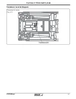
Страница 109: ...250 Outrage Section 4 Electrical System Transducer Location Diagram Transducer Location Fig 4 7 1 TRANSDUCER ...
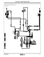
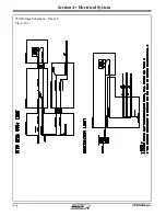
Страница 111: ...250 Outrage Section 4 Electrical System 250 Outrage Schematic Sheet 1 Fig 4 9 1 ...
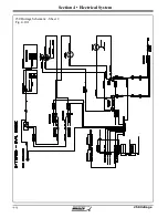
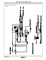
Страница 112: ...250 Outrage Section 4 Electrical System 250 Outrage Schematic Sheet 2 Fig 4 10 1 ...
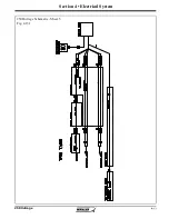
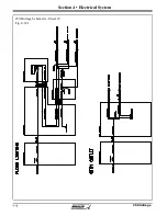
Страница 113: ...250 Outrage Section 4 Electrical System 250 Outrage Schematic Sheet 3 Fig 4 11 1 ...
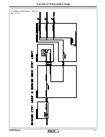
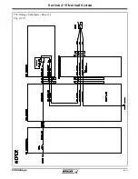
Страница 114: ...250 Outrage Section 4 Electrical System 250 Outrage Schematic Sheet 4 Fig 4 12 1 ...
Страница 115: ...250 Outrage Section 4 Electrical System 250 Outrage Schematic Sheet 5 Fig 4 13 1 ...
Страница 116: ...250 Outrage Section 4 Electrical System 250 Outrage Schematic Sheet 6 Fig 4 14 1 ...
Страница 117: ...250 Outrage Section 4 Electrical System 250 Outrage Schematic Sheet 7 Fig 4 15 1 ...
Страница 118: ...250 Outrage Section 4 Electrical System 250 Outrage Schematic Sheet 8 Fig 4 16 1 ...
Страница 119: ...250 Outrage Section 4 Electrical System 250 Outrage Schematic Sheet 9 Fig 4 17 1 ...
Страница 120: ...250 Outrage Section 4 Electrical System 250 Outrage Schematic Sheet 10 Fig 4 18 1 ...
Страница 121: ...250 Outrage Section 4 Electrical System 250 Outrage Schematic Sheet 11 Fig 4 19 1 ...
Страница 122: ...250 Outrage Section 4 Electrical System 250 Outrage Schematic Sheet 12 Fig 4 20 1 ...
Страница 123: ...250 Outrage Section 4 Electrical System 250 Outrage Schematic Sheet 13 Fig 4 21 1 ...
Страница 124: ...250 Outrage Section 4 Electrical System 250 Outrage Schematic Sheet 14 Fig 4 22 1 ...
Страница 125: ...250 Outrage Section 4 Electrical System 250 Outrage Schematic Sheet 15 Fig 4 23 1 ...
Страница 126: ...250 Outrage Section 4 Electrical System 250 Outrage Schematic Sheet 16 Fig 4 24 1 ...
Страница 127: ...250 Outrage Section 4 Electrical System 250 Outrage Schematic Sheet 17 Fig 4 25 1 ...
Страница 128: ...250 Outrage Section 4 Electrical System 250 Outrage Schematic Sheet 18 Fig 4 26 1 ...
Страница 129: ...250 Outrage Section 4 Electrical System 250 Outrage Schematic Sheet 19 Fig 4 27 1 ...
Страница 130: ...250 Outrage Section 4 Electrical System 250 Outrage Schematic Sheet 20 Fig 4 28 1 ...
Страница 131: ...250 Outrage Section 4 Electrical System 250 Outrage Schematic Sheet 21 Fig 4 29 1 ...
Страница 132: ...250 Outrage Section 4 Electrical System THIS PAGE INTENTIONALLY LEFT BLANK ...
Страница 143: ...Section 5 Care Maintenance 250 Outrage Reinforcement Location Diagram ...

