background image

6720880441 (2018/01)

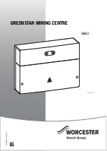
GREENSTAR WIRING CENTRE

1

2

3

4

I

S

Y

0

40

50

II

60

70

max

off

EMS 2

0010016703-001

Содержание WORCESTER GREENSTAR

Страница 1: ...6720880441 2018 01 GREENSTAR WIRING CENTRE 1 2 3 4 I S Y 0 40 50 II 60 70 max off EMS 2 0010016703 001 ...

Страница 2: ... with instructions may result in material damage and personal injury including danger to life Read the installation instructions heat source heating controller etc before installation Observe the safety instructions and warnings Observe national and regional regulations technical rules and guidelines Document all work carried out 1 Explanation of symbols and safety instructions 2 1 1 Explanation o...

Страница 3: ...ser for safekeeping H Damage caused by frost The solar system can freeze if it is switched off Observe the notices regarding frost protection Duetotheadditionalfunctions e g DHWheatingor anti seizing function the system should always be left on Correct any faults immediately 2 Product Information In these instructions the Greenstar Wiring Centre will be referred to as the module The module control...

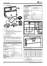
Страница 4: ...t 2 4 Cleaning and care If required wipe the casing with a damp cloth Never use aggressive or acidic cleaning agents for this Specifications Dimensions W H D 151 184 61 mm further dimensions Fig 2 Maximum conductor cross section Terminal 230 V Extra low voltage terminal 2 5 mm2 1 5 mm2 Rated voltages BUS Module power supply User interface Pump and mixer 15 V DC 230 V AC 50 Hz 15 V DC reverse polar...

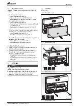
Страница 5: ... Cylinder primary pump connection to PZ1 Cylinder temperature sensor connection to TC1 Installation of additional accessories Fit additional accessories according to legal requirements and the installation instructions supplied The Greenstar Wiring Centre is compatible with the following Worcester plug in wireless programmable devices and room temperature dependent controllers 7733 600 001 Comfort...

Страница 6: ...r cross section 300 m with 1 50 mm2 conductor cross section To avoid inductive interference make sure all low voltage cables are routed separately to mains voltage cables min clearance 100 mm In the case of external inductive interferences e g from PV systems use shielded cables e g LIYCY and earth the shield on oneside Theshieldshouldbeconnectedtothebuilding searthlead e g to a free earth conduct...

Страница 7: ...ly is not provided via the electronic circuitry of the heat source install a circuit breaker complying to the applicable standards to interrupt all phases of the power supply acc to EN 60335 1 The module cover needs to be removed to carry out the electrical connections Only use electric cable of similar quality Ensure that the power supply is connected to the live neutral and earth terminals Elect...

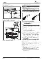
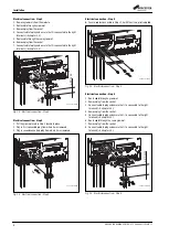
Страница 8: ... from where it was removed Fig 14 Electrical connection Step 4 Electrical connection Step 5 Secure cables connected in Steps 1 4 with the strain relief supplied Fig 15 Electrical connection Step 5 Electrical connection Step 6 1 Route cable through a grommet 2 Remove plug from the socket 3 Connect cable to plug and ensure that it is connected to the right terminals chapter 3 3 4 Remove plug from th...

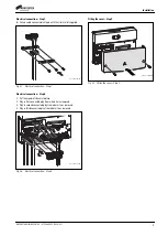
Страница 9: ...trical connection Step 8 1 Put the grommets back into place 2 Plug in first connected plug from where it was removed 3 Plug in second connected plug from where it was removed 4 Plug in third connected plug from where it was removed Fig 18 Electrical connection Step 8 Fitting the cover Step 9 Fig 19 Fitting the cover Step 9 0 010 013 196 001 2 2 4 4 3 3 1 1 0 010 013 197 001 0 010 013 198 001 ...

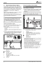
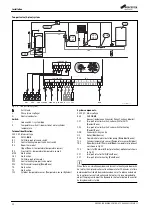
Страница 10: ... lead L Phase mains voltage N Neutral conductor I Code switch I system type II Temperature switch II domestic hot water cylinder temperature BUS BUS EMS 2 Protection of unvented domestic hot water cylinders NOTICE Greenstar Wiring Centre fault isolation Never take the feed to the safety limit thermostat through the control thermostat The cylinder will never reach the temperature set using temperat...

Страница 11: ...e TC1 Cylinder temperature sensor Temperature sensor Cylinder TR3 Roomthermostat ThermostatRoomtemperature optional not shown in Fig 20 TF4 Froststat ThermostatFrostprotection optional notshown in Fig 20 VZ12 Divertervalve ValveZone connectasfollows green yellow to PZ1 blue to PZ1 N grey to PZ1 14 white to PZ2 43 orange to PZ2 no description no function When there is a simultaneous demand for cent...

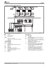
Страница 12: ...ing Contact Zone GWC Greenstar Wiring Centre HS Boiler Heat Source PHS Domestic hot water circulation pump Pump Heat Source TC1 Cylinder temperature sensor Temperature sensor Cylinder TR3 Roomthermostat ThermostatRoomtemperature optional not shown in Fig 21 TF4 Froststat ThermostatFrostprotection optional notshown in Fig 21 VZ1 Two port valve for DHW Valve Zone VZ2 Two port valve for heating Valve...

Страница 13: ...allocation of heating units 1 2 and 3 or 4 5 and 6 according to coding chapter 4 page 15 T0 Flow temperature sensor at the low loss header Temperature sensor optional TZ1 6 Room thermostat Thermostat room temperature Zone temperature temperature sensor allocation of heating circuits 1 2 and 3 or 4 5 and 6 according to coding chapter 4 page 15 The marked system components are connected to the modul...

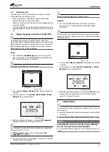
Страница 14: ...ar Wiring Centre through the DHW cylindersafetythermostat Thisensuresthatwhenthesafetythermostat is tripped the heat source is isolated Commissioning the Greenstar Wiring Centre The required settings of the dial on the front of the Greenstar Wiring Centre are shown in Fig 25 In the event of the hot water dial indicator flashing green adjust the hot water temperature selector dial in small incremen...

Страница 15: ...t 1 will appear automatically on the room thermostat For 2 zone heating 1 hot water solution when pairing a second room thermostat 8 716 117 239 if HC Assignment 1 appears this must be changed to HC Assignment 2 using the dial 5 Pressthedialandthemainscreenappears Thereceiver sLEDstops flashing Pairing is now complete The receiver pairing mode lasts for up to one minute Unpairing 1 Press the Overr...

Страница 16: ...system the Greenstar Wiring Centre and the boiler When the status indicator of module lights up green 4 Commission and set up the boiler and control system accessories in accordance with the installation instructions supplied with those products 5 Troubleshooting Use only original spare parts Damage caused by the use of spare parts not supplied by the manufacturer are excluded from the warranty If...

Страница 17: ...ctly observed To protect the environment we use the best possible technology and materials while taking into account economic considerations Packaging Where packaging is concerned we participate in country specific recycling processes that ensure optimum recycling Allofourpackagingmaterialsareenvironmentallycompatibleandcanbe recycled Old electrical and electronic appliances Electrical or electron...

Страница 18: ......

Страница 19: ......

Страница 20: ...roup is a brand name of Bosch Thermotechnology Ltd worcester bosch co uk 6720880441 WORCESTER BOSCH GROUP TECHNICAL SUPPORT 0330 123 3366 CONTROLS AND CONNECTIVITY TEAM 0330 123 3641 APPOINTMENTS 0330 123 9339 SPARES 0330 123 9779 LITERATURE 0330 123 9119 TRAINING 0330 123 0166 SALES 0330 123 9669 ...

Отзывы: