Installation
GREENSTAR WIRING CENTRE – 6720880441 (2018/01)
12
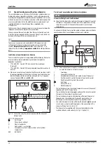
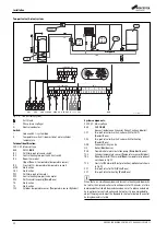
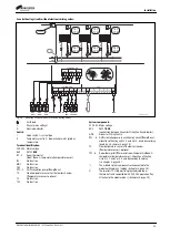
Two-port valve (S-plan) system:
Fig. 23 Two-port valve system
Earth lead
L
Phase (mains voltage)
N
Neutral conductor
Switch:
I
Code switch I – system type
II
Temperature switch II – domestic hot water cylinder
temperature
Terminal identification:
230 V AC Mains voltage
BUS
EMS 2
BUS
IZ1
DHW two-port valve end switch
IZ2
Central heating two-port valve limit switch
IZ3
Room thermostat
(
I
nput
Z
one;
: temperature/temperature sensor)
IZ4
Frost stat (
: temperature/temperature sensor)
MD1
No function
OS1
No function
PZ1
DHW two-port valve motor
PZ2
Central heating two-port valve motor
PZ3
DHW circulation pump (
P
ump
Z
one)
T0
No function
T1
No function
TC1
Cylinder temperature sensor (
T
emperature sensor
C
ylinder)
System components:
230 V AC Mains voltage
BUS
EMS 2
BUS
(connection between Greenstar Wiring Centre and boiler)
CZ1
Two-port valve limit switch, valve switch for DHW
(
C
ontact
Z
one)
CZ2
Two-port valve limit switch, valve switch for heating
(
C
ontact
Z
one)
GWC
Greenstar Wiring Centre
HS
Boiler (
H
eat
S
ource)
PHS
Domestic hot water circulation pump (
P
ump
H
eat
S
ource)
TC1
Cylinder temperature sensor (
T
emperature sensor
C
ylinder)
TR3
Room thermostat (
T
hermostat
R
oom temperature); optional;
not shown in Fig. 21
TF4
Frost stat (
T
hermostat
F
rost protection); optional; not shown
in Fig. 21
VZ1
Two-port valve for DHW (
V
alve
Z
one)
VZ2
Two-port valve for heating (
V
alve
Z
one)
When there is a simultaneous demand for central heating and domestic
hot water, the S-plan diverter valve will operate for 10 minutes at a time
between both until both demands have been met. To reduce extended
heat-up times for central heating and hot water, it is recommended to
adjust the program to meet the demand for hot water before the central
heating demand is started
HS
GWC
PHS
TC1
VZ1
CZ1
VZ2
CZ2
0010016318-001
1
2
1
2
1
2
TC1
T0
BUS
BUS
1
2
BUS
1
2
3
1
OS1
2
1
2
MD1
1
2
T1
24 V
N L
N
L
N
IN L IN L IN L IN
L
120/230VAC
120/230VAC
IZ1
IZ2
IZ3
IZ4
120/230 V AC
N
N 43
N 14
14
PZ2
PZ3
PZ1
120/230 V AC
230 V AC 230 V AC
L
N
L
N
BUS
TC1
M
VZ1
N L
L
N
N
M
VZ2
N L
L
M
PHS
N L
L
N
CZ1 CZ2
TR3
L
S
TF4
L
S
I
II
II
0
1
2
3
4
S
Y
off
off
40
40
50
50
60
60
70
70
max
max

