Installation
GREENSTAR WIRING CENTRE – 6720880441 (2018/01)
10
3.3
Connection diagrams with system schematics
The circuit diagrams are only schematic illustrations and provide a non-
binding indication of possible installations. Install safety equipment in
accordance with applicable standards and local regulations. For further
information refer to the installation instructions of the boiler and control
accessory selected or for the the additional system components (not
supplied by Worcester, Bosch Group) those supplied by the
manufacturer.
The Worcester, Bosch Group customer service may be contacted on the
telephone number on the back of these instructions.
When using any other controls other than Worcester Comfort controls,
install the jumper supplied with the Greenstar Wiring Centre which can
be found in the bag with the installation materials.
To ensure an economical and comfortable DHW temperature and
sufficient protection against bacterial contamination in the DHW
cylinder,
temperature switch II
should be set to at least 60 °C. To
reduce the risk of scalding,
temperature switch II
should be set below
60 °C.
Installation of room thermostat or link wire
The Greenstar Wiring Centre is compatible with the following Worcester
plug-in wireless programmable devices and room temperature-
dependent controllers:
• 7733 600 001; Comfort I RF twin-channel timer and room
thermostat
• 7733 600 002; Comfort II RF programmable room thermostat and
receiver
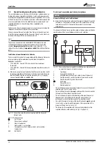
▶ When using any other controls other than Worcester controls, install
the jumper supplied with the Greenstar Wiring Centre which can be
found in the bag with the installation materials (
connect terminals
IZ3 – L
and
IZ3 – IN
.
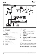
Fig. 20 Connection using the jumper supplied with the Greenstar
Wiring Centre
230 V AC Mains voltage
Earth lead
L
Phase (mains voltage)
N
Neutral conductor
I
Code switch I – system type
II
Temperature switch II – domestic hot water cylinder
temperature
BUS
BUS EMS 2
Protection of unvented domestic hot water cylinders
NOTICE:
Greenstar Wiring Centre fault isolation!
▶ Never take the feed to the safety limit thermostat through the control
thermostat. The cylinder will never reach the temperature set using
temperature switch II if the control thermostat is set at a lower
temperature.
The Greenstar Wiring Centre must be wired as follows when installed in
combination with an unvented domestic hot water cylinder:
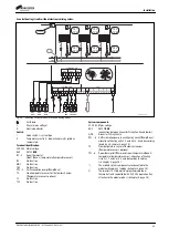
Fig. 21 Connection of power supply for installation in combination with
an unvented domestic hot water cylinder
1
Fused spur
2
Greenstar Wiring Centre
3
Unvented domestic hot water cylinder's dual thermostat
4
Dual thermostat's control thermostat (must not be used)
5
Dual thermostats high limit thermostat
Earth lead
L
Phase (230 V AC)
N
Neutral conductor
• The installation will use the cylinder temperature sensor (Greenstar)
supplied with the TC1 Wiring Centre.
• The installation therefore does
not
need to use the hot water control
thermostat of the cylinder's dual thermostat.
• The installation may require altered wiring of the dual thermostat
(depending on the cylinder and thermostat manufacturer) to
exclusively use the safety thermostat of the dual thermostat.
• The safety thermostat section of the dual thermostat
must
be wired
in such a way as to interrupt the permanent live connection to the
Greenstar Wiring Centre (
• The two-port valve supplied with the unvented cylinder must be
installed and connected correctly (
0
1
2
3
4
S
Y
I
off
off
40
40
50
50
60
60
70
70
max
max
II
II
230 V AC 230 V AC
L
N
L
N
BUS
0 010 017 134-001
1
2
1
2
1
2
TC1 T0
BUS
BUS
1
2
BUS
1
2
3
1
OS1
2
1
2
MD1
1
2
T1
24 V
N L
N
L
N
IN L IN
L IN
L IN
L
120/230VAC
120/230VAC
IZ1
IZ2
IZ3
IZ4
120/230 V AC
N
N 43
N 14
14
PZ2
PZ3
PZ1
120/230 V AC
1
2
BUS
N L
120/230VAC
. . . . .
L N
0 010 017 138-001
2
3
4
5
1

