Installation
GREENSTAR WIRING CENTRE – 6720880441 (2018/01)
14
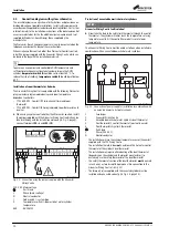
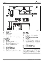
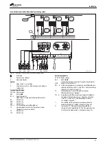
2 heating circuits without electronic mixing valves and one
domestic hot water cylinder circuit (S-plan Plus), with 2x Comfort II
RF programmable room thermostats for load compensation:
Fig. 25
3.4
Installing the system
Worcester products required:
▶ Greenstar i System OR i System compact boiler (without optional
internal diverter kit), OR regular Greenstar 27/30 Ri boiler
▶ Comfort II RF Programmable room thermostat pack
(7-733-600-002)
▶ Additional Comfort II RF Programmable room thermostat
(8-716-117-239)
▶ Greenstar Wiring Centre manufactured from December 2016
(FD 660)
This solution is not compatible with the Greenstar CDi Classic System
boiler.
Fig. 25 is a schematic diagram intended to demonstrate how a system
utilising these products might be laid out. Detail is included for what
system fixtures are wired to the Wiring Centre in the form of labels and a
key.
2-port motorised zone valves must be of the spring return type. Only the
3 motor wires of each zone valve are used (live, neutral conductors and
earth lead). The remaining switch wires (for example: orange, grey,
white) are unused.
If installing this system with the Greenstar 27/30 Ri boiler, the external
pump must be wired back to the boiler’s dedicated pump live, neutral
conductors and earth lead. Refer to the boiler’s specific installation
instructions for more detail.
Unvented DHW cylinder G3 compliance
If using an unvented DHW cylinder, G3 compliance can be achieved by
supplying the power to the Greenstar Wiring Centre through the DHW
cylinder safety thermostat. This ensures that when the safety thermostat
is tripped, the heat source is isolated.
Commissioning the Greenstar Wiring Centre
The required settings of the dial on the front of the Greenstar Wiring
Centre are shown in Fig. 25.
In the event of the hot water dial indicator flashing green, adjust the hot
water temperature selector dial in small increments to select a valid
temperature setting. Only temperatures indicated on the control dial can
be selected. Once set correctly, the hot water temperature selector dial
indicator will cease to flash.
In order to provide effective protection against legionella, the domestic
hot water temperature should be set to at least 60 °C degrees.
If the green light continues to flash once a valid temperature has been
selected, see chapter 26, page 16 for further guidance.
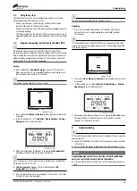
Commissioning the Comfort II RF
Comfort II RF (7-733-600-002)
comes pre-paired with its receiver and
is used to control zone 1 and sanitary hot water heating. It does not
require pairing.
Comfort II RF (8-716-117-239)
must be paired with the same receiver
unit and is used to control zone 2 central heating.
0010017154-001
II
II
II
0
1
2
3
4
S
Y
off
off
40
40
50
50
60
60
70
70
max
max
Key
Mains Cold Water
Domestic Hot Water
Primary Flow
Primary Return
Comfort II RF components
Greenstar Wiring Centre
Motorised Zone Valve 2-port
M
M
M
Balanced
Cold Feed
M
N 14
PZ1
N 43
PZ2
N 14
PZ3
N L
230
VAC
N L
230
VAC
L
N
IN
IZ1
L IN
IZ2
L IN
IZ3
L IN
IZ4
1 2
TC1
1 2
TO
1 2
T1
2
1
3
OS1
1 2
MD1
1 2
BUS
1 2
BUS
1 2
BUS
L
N
IN
IZ1
L IN
IZ2
L IN
IZ3
L IN
IZ4
1 2
TO
1 2
T1
2
1
3
OS1
1 2
MD1
1 2
BUS
1 2
BUS
Zone 1
Zone 2
1
3
2
4
5
1
2
3
4
5
Greenstar
Wiring Centre
Connections &
Settings
GWC

