Troubleshooting
GREENSTAR WIRING CENTRE – 6720880441 (2018/01)
16
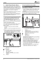
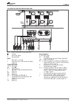
Code switch I
The system type is set on the module using
code switch I
:
• 3-way valve (Y-plan) system: code switch I set to
Y
• Two-port valve (S-plan) system: code switch I set to
S
• 3 central heating circuits without electronic mixing valves:
– Module for heating circuits 1, 2 and 3 = set code switch 1 to
2
– Module for heating circuits 4, 5 and 6 = set code switch I to
3
• 2 heating circuits without electronic mixing valves and one cylinder
charging circuit: set code switch I to
1
Temperature switch II
WARNING:
Risk of scalding from hot water!
▶ If water temperatures are set above 60 °C or thermal disinfection is
engaged (where temperature switch II is temporarily over 60 °C), a
mixer must be installed.
Automatic legionella protection function: this function becomes active if
the DHW cylinder does not reach a temperature of 60 °C during a 5-day
period. This function automatically heats the cylinder 65 °C for 2 hours.
The
cylinder setpoint temperature
is adjusted using
temperature
switch II
:
• The temperature in the DHW cylinder can be adjusted in increments
of 5 °C.
• To ensure an economical and comfortable DHW temperature and
sufficient protection against bacterial contamination in the DHW
cylinder,
temperature switch II
should be set to at least 60 °C.
• A maximum setpoint temperature 75 °C is available: set the
temperature switch to
max
(two valid switch positions)
In the event of the hot water dial indicator flashing green, adjust the hot
water temperature selector dial in small increments to select a valid
temperature setting. Only temperatures indicated on the control dial can
be selected. Once set correctly, the hot water temperature selector dial
indicator will cease to flash.
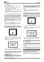
System and module commissioning
1. Set the system type for the module using code switch
I
.
2. Set the cylinder temperature using temperature switch
II
.
-or-
Set temperature switch
II
to
off
.
3. Switch on the power supply (230 V AC) for the entire system, the
Greenstar Wiring Centre and the boiler.
When the status indicator of module lights up green:
4. Commission and set up the boiler and control system accessories in
accordance with the installation instructions supplied with those
products.
5
Troubleshooting
Use only original spare parts. Damage caused by the use of spare parts
not supplied by the manufacturer are excluded from the warranty.
▶ If a fault cannot be rectified, please contact your local service
engineer.
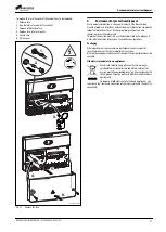
5.1
Status indicator
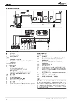
The indicator shows the operating status of the module.
Fig. 26 Module status indicator
Table 4 Troubleshooting
5.2
Replacing the fuse
DANGER:
Danger to life due to current!
Touching live parts can result in an electric shock.
▶ Electrically isolate the boiler and system components. Secure against
unintentional reconnection and make sure the power supply is
disconnected.
Status indicator
Possible cause
Remedy
permanently off
(at code switch I)
Code switch on
0
▶ Set the code switch
(
Power supply
interrupted
▶ Turn on the power supply.
Fuse is defective
▶ With the power supply turned
off, replace the fuse
(
Short circuit in the BUS
connection
▶ Check BUS connection and
repair if required.
permanently red
(at code switch I)
Internal fault
▶ Replace module.
Flashing red (on
code switch I)
Code switch in invalid
position or in
intermediate position
▶ Set the code switch
(
Flashing green (on
code switch I)
Maximum cable length
for BUS connection
exceeded
▶ Make shorter BUS
connection.
Temperature sensor is
defective
▶ Replace the temperature
sensor.
Temperature switch in
invalid position or in
intermediate position
▶ Adjust the temperature
switch (
No signal from the 2-
way zone valve limit
switch received within
30 seconds after
commissioning
▶ Check the cabling between
the zone valve and zone valve
limit switch
Temperature for
legionella protection not
reached in the 2-hour
phase
▶ Insufficient heat transfer via
the cylinder ignition coil, or;
▶ Check the sensor position on
the cylinder.
Permanently
green (at code
switch I)
No fault
Normal operation
0
1
2
3
4
S
Y
I
off
40
50
60
70
max
II
II
0 010 013 180-001


