Repair and Testing Instructions for T1 Page 36
Alternator 0120 689 552
Edition 001
All rights rest with Robert Bosch Corp, including patent rights. All rights of use of reproduction and publication rest with R. B. Corp.
UA/ASV
04.12.98
T1ALTFinal.DOC
3. Connect the test leads of the test bench to the alternator as follows:
a. Connect the +24 v lead of the test bench to the B+ terminal of the alternator.
b. Connect the -24 v lead of the test bench to the B- terminal of the alternator.
c. Connect the charging indicator lamp of the test bench to the D+ terminal of the alternator.
Note: Refer to test bench manufacturers operating instructions for correct terminology of test leads
Refer to figure 39 for a schematic outline of alternator to test bench connections. Compare this schematic
to the hook-up schematic of your test bench.
4. Make sure the test bench is set for the correct voltage and rotation before starting tests.
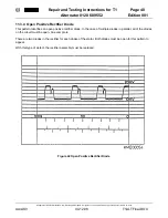
11.2.2 Power Output Test
1. Start test bench and increase speed to 1500 rpm, alternator speed.
2. Increase inductive load on the alternator until 76A output is achieved. As load is increased, monitor test
bench speed and correct if speed drops while applying load.
Figure 39 Alternator Test Bench Hook-up Schematic
(1) Variable Load Resistor
(2) Ammeter (Alternator Output)
(3) Charging Indicator Lamp
(4) Voltmeter (Regulated Voltage)
(5) Ammeter
(6) Test Bench Battery


