Repair and Testing Instructions for T1 Page 30
Alternator 0120 689 552
Edition 001
All rights rest with Robert Bosch Corp, including patent rights. All rights of use of reproduction and publication rest with R. B. Corp.
UA/ASV
04.12.98
T1ALTFinal.DOC
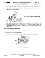
10. With tool KDLJ 6015, press sliding bushing into end shield until the bushing is flush with the inner surface of
the mounting/pivot boss. (Figure 30)
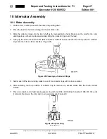
11. Insert terminal W into collector end shield in location marked W. Make sure the locating lug of the terminal
assembly indexes the end shield correctly.
12. Place insulator and flat washer onto terminal W.
13. Install nut and torque to 4.1 to 5.5 Nm (36.3 to 48.7 in. lbs.)
14. Install protective cap onto terminal W. (Figure 31)
Protective Cap
10.4 Rectifier Assembly
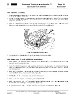
1. Place flat washer and insulator (a) onto terminal B+ and D+ studs of the rectifier assembly. (Figure 32)
Figure 30 Sliding Bushing Installation
Figure 31 Terminal W Insulator,
Washer, Nut and Cap
Figure 32 Rectifier Insulators and Seal


