Ball bearing pinion or helical drive
pinion
Owing to thermal effects, the flange-sided end of the output shaft may shift by
0.6 mm in relation to the motor housing. If helical drive pinions or bevel gear
pinions directly attached to the output shaft are used, this change in position
will lead to
●
a shift in the position of the axis, if the driving pinions are not defined
axially on the machine side,
●
a thermally dependent component of the axial force, if the driving pin‐
ions are defined axially on the machine side. This causes the risk of ex‐
ceeding the maximum permissible axial force or of the play within the
gears increasing to an impermissible degree.
In such cases, you should therefore preferably use drive elements
with their own bearings which are connected to the motor drive
shaft via axially compensating couplings.
9.12
Holding Brakes (Ex)
9.12.1
Holding Brake Electrically-Released
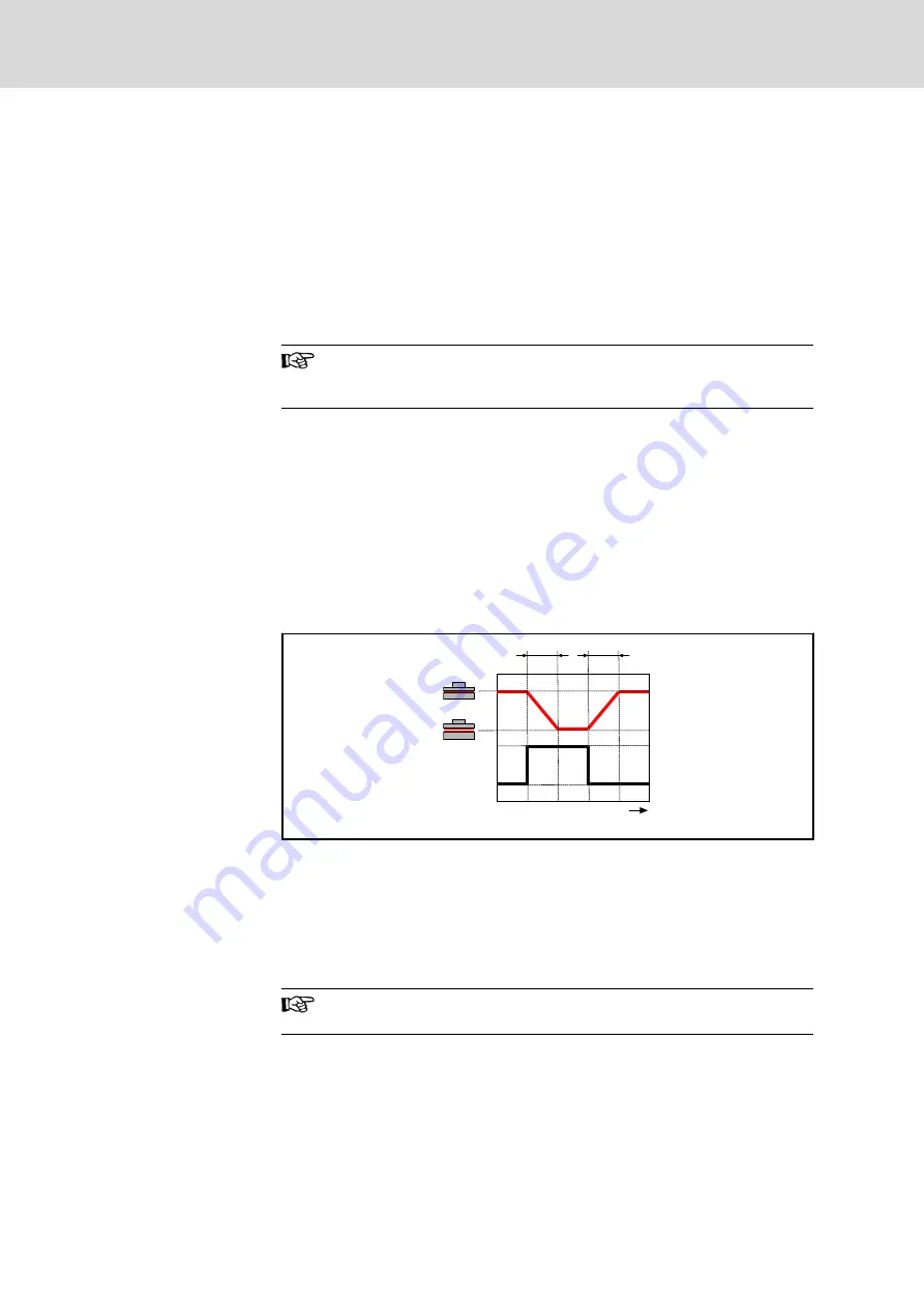
The holding brake of the IndraDyn S motors works according to the principle
"electrically-released". Non-operative closed holding brakes open when ap‐
plying the operating voltage.
The voltage supply of the holding brake has to be designed so as to guaran‐
tee under the worst installation and operation conditions that a sufficient volt‐
age (24 V ±10%) is available at the motor in order to release the holding
brake.
t
U
N
[V]
0
24
MKE00106
t
2
t
1
t
1
Connection time
t
2
Disconnection time
Fig.9-20:
Switching status of holding brake over time
The electrically releasing holding brake is used to hold the axes at a standstill
and when the ”controller enable” signal is off. When the supply voltage fails
and the controller is enabled, the electrically-releasing holding brake will
close automatically.
Do not use the holding brake as an operating brake for moving
axes.
If the holding brake is repeatedly activated with the drive rotating or the al‐
lowed braking energy is exceeded, premature wear and tear may occur.
9.12.2
Holding Brakes - Notes Regarding Safety
Observe the safety requirements for the system planning and development.
Bosch Rexroth AG
DOK-MOTOR*-MKE*GEN2***-PR06-EN-P
Rexroth MKE Synchronous Motors for Potentially Explosive Areas acc. to ATEX and UL/CSA
90/135
Operating Conditions and Application Notes
LSA Control S.L. www.lsa-control.com [email protected] (+34) 960 62 43 01


