background image

HPC Board Replacement and Installation

 | 

25

Heat Pump Controller

8733819577 (2019/02)

Heat Pump Controller

Subject to change without prior notice

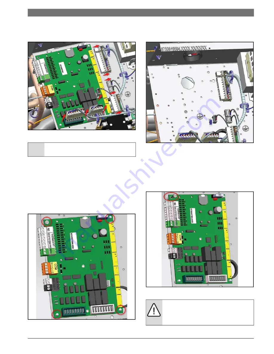
3. Move the plugs to the side to allow room to 

access the standoffs and the ground screw.

Fig. 16      HPC Wiring Disconnected

4. Once the plugs are removed:

Use a 1/4” Hex driver to remove the ground 
screw.

Use the needle nose pliers to remove the 
PCB from the plastic standoffs.

Push on the standoff's tabs and pull the 
PCB from the bottom to detach it from 
electrical box.

Fig. 17      Standoffs and Ground Screw

5. Once the controller is detached, place the new 

controller in the existing footprint.

Fig. 18      HPC Board Removed

6. Secure the PCB via the standoffs.
7. Double-check that the controller is secured 

and attached to the electrical box.

8. Use the 1/4” hex driver to secure the ground 

screw to the electrical box’s metal plate.

Fig. 19      Ground Screw Circled

NOTICE

: Make sure that the plugs are 

moved to the side to avoid wire damage.

WARNING

: The ground screw must be 

connected as it provides earth ground to 
the controller. There is potential for electric 
shock if not grounded properly.

Содержание HPC

Страница 1: ...Installation Operation and Maintenance Manual HPC 8733819577 2019 02 Heat Pump Controller ...

Страница 2: ...ing Mode Operation 12 Unlatching Mode Factory Default 12 System Protection 13 Consumer Enhanced Security 13 Compressor Demand Y1 Call 13 Pressure Protection 13 Brownout Protection 14 Low Loop Water Protection Control LLWPC Boilerless Control 14 Water Flow Detection 14 Sensor Monitoring 14 Troubleshooting 19 Invalid Thermostat Demands 19 Replacement Parts 19 Unit Status LED Blink Code Information 2...

Страница 3: ... risk are not taken This symbol indicates important information where there is no risk to property or people IMPORTANT Read the entire instruction manual before starting installation WARNING Installation and servicing of this equipment can be hazardous due to system pressure and electrical components Only trained and qualified personnel should install repair or service the equipment WARNING Before...

Страница 4: ...perating conditions and faults when they arise via the Bosch EasyStart app interface Fig 1 Heat Pump Controller Table 1 Available Fault Snapshots Item No Description 1 HPC Ground Standoff 2 Thermostat Power Source 3 Thermostat Control Signals 4 Humidistat Control Signals 5 Comm Port RS 485 6 Electric Heat 1 Output 7 Electric Heat 2 Output 8 Display Output 9 Alarm Output Dry N O 10 Heat Pump Contro...

Страница 5: ...scharge Refrigerant Temperature DRT Domestic Water Temperature DWT Digital Outputs Rated 24VAC Compressor 1st step control CC1 Compressor 2nd step control CC2 Reversing valve control RV Auxiliary Output1 Aux Heat control AUX1 Auxiliary Output2 Aux Heat control AUX2 Alarm purposes dry contact normally open NO Pulse or Constant ALM Digital Outputs Rated 208 230 VAC Loop valve pump control 5 Amp Max ...

Страница 6: ...n there is a call for compressor operation This loop pump control relay is used to switch 208 240 VAC signals ON OFF depending on the supply voltages WARNING Chassis Ground Ensure metal standoff is properly secured to the chassis of the unit through a fastener The HPC will obtain a chassis ground by way of a metal standoff connected to both the C GND and C terminals of the Printed Circuit Board PC...

Страница 7: ...ed Heat Recovery Setpoint 110 F 140 F 120 F Heat Recovery Sample Rate 2 6 Samples Hr 3 Samples Hr Electric Heat Size None 5kW 10kW 15kW 20kW None Low Loop Water Protection Enabled or Disabled Disabled Low Loop Control Setpoint 20 F 50 F 34 F Loop Pump Compressor Delay 30 240 seconds 30s Mode of Compressor Operation Comfort or Economy Comfort Down Staging Latched or Unlatched Unlatched Number of Lo...

Страница 8: ...r reset option using the Bosch EasyStart app Fan Motor The installer can modify the total Cubic Feet per Minute CFM Ton via the Bosch EasyStart app as shown in the table below Table 3 CFM Configure The controller calculates the required flow rate CFM based on the unit s model and size The controller has a cooling CFM Ton lower limit of 270 If effective CFM is lower than this value the controller w...

Страница 9: ...SC will not be in effect during a Random Start Up delay Snapshot Record The controller constantly monitors all thermostat sensors and thermostat demand values The controller also has an additional feature where the latest fault snapshot will be saved to the controller When a new fault occurs the snapshot will be saved and overwrite the previous snapshot The following faults in the table below will...

Страница 10: ...eceived on the thermostat interface block The fan will run at its minimum factory speed of 80 in fan only mode The fan remains on during lockouts if there is a demand from the thermostat The fan motor will take 10 seconds to ramp up to operating speed The fan can be configured via the Bosch EasyStart app to run in a range of CFM from 300 to 450 in 25 CFM increments The controller has airflow profi...

Страница 11: ...ge of electric heat stage 2 after a 180 second delay Heat Recovery Package HRP The HRP can be used to heat potable water during unit operation heat that would otherwise be wasted from the compressor discharge gas The HRP consists of three major components Double wall vented refrigerant to water heat exchanger HRP pump Control circuit Conditions for the HRP to operate are as follows 1 Discharge Ref...

Страница 12: ... rest the ground loop between cooling and heating cycles thus increasing the capacity for heat exchange Performance efficiency and comfort provided by a WSHP will largely be maintained by preventing the degradation of the loop s physical heat exchange properties During latching mode operation the unit will fasten the two compressor outputs together until the demand is satisfied If the thermostat r...

Страница 13: ...two second pause in between the flash sequence The sequence or flash grouping will be repeated until the fault is cleared The LED will only flash one error code until it is cleared See Clearing a Hard Lockout on page 8 Low Pressure Switch LPS The LPS prevents the unit from running in a condition of low refrigerant pressure If the LPS is open the compressor will not energize even if there is a dema...

Страница 14: ...oling mode for 90 seconds If LWT is 5 F to 15 F higher than the EWT the unit is running in nominal operating conditions If LWT and EWT are the same and the compressor is enabled CS1 the FZC and Freeze Evaporator Coil FZE temperatures are sampled every 10 seconds for 30 seconds Rapid temperature changes on the freeze sensors will be used by the controller to report a No Water Flow fault and de ener...

Страница 15: ...3 Fig 3 DAT Sensor Location Return Air Temperature RAT Sensor The RAT sensor is installed in front of the filter bottom right corner and connected to the HPC It reads the RAT to determine whether the unit is operating in the correct state according to the thermostat demand The RAT works together with the DAT sensor to determine if there is a fault either Not Cooling Heating with Cooling Demand Not...

Страница 16: ...LWT Sensor Location Entering Water Temperature EWT Sensor An EWT sensor is installed on the entering water pipe of the coaxial water coil The location of the EWT sensor is shown on Fig 7 Cooling Mode High EWT above 110 5 F for one minute will result in a warning message indicating an high EWT fault without impeded operation This fault will reset when EWT drops below 105 F Heating Mode Low EWT acti...

Страница 17: ...g refrigerant pipe after the thermal expansion device and before the air coil The location of the FZE is shown on Fig 9 The freeze limit trip is set to factory default at 30 F If the temperature drops below or remains constant at the freeze point for more than 30 seconds after the compressor is energized the controller will shut down the compressor to prevent freezing the air evaporator coil The c...

Страница 18: ...tively and can be adjusted via the Bosch EasyStart app The controller will run the pump four times hour adjustable two to six times hour via Bosch EasyStart app to determine whether or not domestic hot water production is needed If the DWT sensor is invalid or not within range a warning message will be sent to the Bosch EasyStart app Location of the DWT sensor is shown in Fig 11 Fig 11 DWT Sensor ...

Страница 19: ...at only the impedance of the thermistor is measured See the table on page 23 for values OUTPUTS The Reversing Valve Compressor Stage 1 Compressor Stage 2 Auxiliary Relay 1 and Auxiliary Relay 2 are 24 VAC and can be verified using a voltmeter The Loop Pump and HRP Pump are 208 or 230 VAC depending on the line voltage connected to the unit These can be verified using a voltmeter and their value mus...

Страница 20: ...ITION 5 Sensed input voltage at or below 18 VAC FREEZE EVAPORATOR SENSOR 6 FZE below temperature limit bypassed for first 30 seconds Troubleshooting Heating Cooling Indicator HTG CLG Behavior Solution Action HEARTBEAT LED X X LED is flashing two times a second Normal HPC Operation X X LED is flashing at a slow rate one flash per second instead of two HPC application program is not running Connect ...

Страница 21: ...rature out of range Verify temperature value with Bosch EasyStart app Bring water temp within design parameters X Reduced air flow Check for dirty air filter and either clean or replace Check fan motor operation and airflow restrictions Review airflow setting with Bosch EasyStart app Dirty Air Coil construction dust etc X Air temperature out of range in heating Bring return air temperature within ...

Страница 22: ... needs attention Thermistor Resistance Versus Temperature Fig 12 Type II Thermistor Temperature Curve If during an HPC firmware update and there is an update failure e g caused by a power outage the control software on the HPC will be corrupted The HPC update failure will place the HPC in safe mode and an update must be performed to restore normal operation Safe mode also known as bootloader mode ...

Страница 23: ...1 214 659 36 33 258 800 10 50 19 900 56 133 2 878 102 216 640 35 31 242 700 11 52 18 970 57 135 2 774 103 217 622 34 29 227 600 12 54 18 090 58 136 2 674 104 219 604 33 27 213 600 13 55 17 260 59 138 2 579 105 221 587 32 26 200 500 14 57 16 470 60 140 2 488 106 223 571 31 24 188 300 15 59 15 710 61 142 2 400 107 225 555 30 22 177 000 16 61 15 000 62 144 2 316 108 226 539 29 20 166 400 17 63 14 330...

Страница 24: ...ial Number Example of a unit data plate is shown in Fig 13 This will be used later to update the configuration of your appliance Fig 13 Example of a Unit Data Plate HPC Board Replacement To replace the controller perform the following steps 1 Use the handle to pull the panel upwards and detach from the unit Fig 14 Electrical Access Panel Removed 2 Identify the standard harnesses connected to the H...

Страница 25: ...CB from the bottom to detach it from electrical box Fig 17 Standoffs and Ground Screw 5 Once the controller is detached place the new controller in the existing footprint Fig 18 HPC Board Removed 6 Secure the PCB via the standoffs 7 Double check that the controller is secured and attached to the electrical box 8 Use the 1 4 hex driver to secure the ground screw to the electrical box s metal plate ...

Страница 26: ...gs Updating the Firmware and Configuring Unit Settings 1 Download and launch the Bosch EasyStart app onto your Android tablet Apple iPad or Windows 7 0 or higher laptops PCs 2 Upon launching the app the splash screen displays and is followed by the Legal information and User Guide screens Fig 21 Splash Screen Fig 22 Legal Information Fig 23 User Guide 3 Once you accept the legal information and re...

Страница 27: ...tep 6 Click the Continue button in the app The Bosch network for the unit displays as shown in Fig 26 Fig 26 Select Network 7 Select the network 8 Next select the connection method either manually entering the password for the network or using the WIM s QR code to automatically enter the password Click the Connect by entering password button then manually enter the password that is printed on the ...

Страница 28: ... newer firmware version as available A list of available versions is displayed Fig 30 Firmware Update 12 Select the version you want to use 1 from the list then click the Flash button 2 The Firmware Update progress is displayed Fig 31 Firmware Update Progress 13 When the firmware update completes click the Done button 1 14 Click the Home icon button to display the Home screen Fig 32 Configure Unit...

Страница 29: ...nter the appropriate settings for the device Pay close attention to make sure the Model and Serial numbers in the app match the model and serial numbers of the device Fig 34 Model Number 1 Serial Number 2 and Send to Unit 3 17 Click the Send to Unit button 3 to write the changes to the device Fig 35 Confirm Saving the Configuration Changes to the Device 18 Click OK 1 to write the configuration to ...

Страница 30: ... Y1 Y2 W1 W2 H RH T1 C T1 R COMM 12 C HPS HPS LPS LPS FZC C FZE COND X X EWT EWT LWT LWT RAT RAT DAT DAT SR C AUX C 10 9 8 7 6 5 4 3 2 1 8 7 6 5 4 3 2 1 4 3 2 1 5 4 3 2 1 X X L1 L2 HRP HRP LP1 LP2 X ERT ERT DWT DWT 24DC RPM PWM GND 1 2 3 4 5 6 7 8 CS1 C CS2 RV C HUM RHV SEL C 1 2 3 4 5 6 7 8 1 2 3 4 HPC F4 3 AMP 2 1 1 2 3 4 5 6 7 8 9 10 SERVICE PORT P1 P2 P3 P4 P5 ALR DISPLAY P6 P7 P8 P9 P10 F5 1A...

Страница 31: ... O Y1 Y2 W1 W2 H RH T1 C T1 R COMM 12 C HPS HPS LPS LPS FZC C FZE CON X X EWT EWT LWT LWT RAT RAT DAT DAT SR C AUX C 10 9 8 7 6 5 4 3 2 1 8 7 6 5 4 3 2 1 4 3 2 1 5 4 3 2 1 X X L1 L2 HRP HRP LP1 LP2 X ERT ERT DWT DWT 24DC RPM PWM GND 1 2 3 4 5 6 7 8 CS1 C CS2 RV C HUM RHV SEL C 1 2 3 4 5 6 7 8 1 2 3 4 HPC F4 3 AMP 2 1 1 2 3 4 5 6 7 8 9 10 SERVICE PORT P1 P2 P3 P4 P5 ALR DISPLAY P6 P7 P8 P9 P10 5 4 ...

Страница 32: ...Heat Pump Controller Heat Pump Controller 8733819577 2019 02 Subject to change without prior notice 32 Electrical Box ELECTRICAL BOX Typical Layout Fig 38 Typical Electrical Box Layout ...

Страница 33: ...ectors Fig 40 Generic Thermostat Connections The HPC also provides visual indication green LED when the Thermostat has a call for a signal ALARM TERMINAL WIRING Fig 41 Alarm Terminal Connectors on the HPC Board Fig 42 Generic Thermostat Connections Fig 43 Alarm Support for Dry Contact Thermostats Fig 44 Alarm Support for 24VAC Thermostats When using a 2 cool 3 heat thermostat both the W1 W2 on the...

Страница 34: ...ireless Interface Module Terms Conditioned space Space within a building provided with heated or cooled air or both or surfaces and where required with humidification or dehumidification means to maintain conditions for an acceptable thermal environment Decommissioning Means the final shut down and removal from operation or usage of a product or piece of equipment containing fluorinated greenhouse...

Страница 35: ...you will help ensure that the waste undergoes the necessary treatment recovery and recycling thus preventing potentially negative effects on the environment and human health which could otherwise arise due to inappropriate waste handling Many parts in the Heat Pump can be fully recycled at the end of the product life Contact your city authorities for information about the disposal of recyclable pr...

Страница 36: ...Ampacity Operating Conditions Cooling Mode Heating Mode Entering Leaving Air Temp Entering Air Measured at Leaving Air Measured at Entering Leaving Fluid Temp Fluid Flow gpm Compressor Volts Amps Blower Motor Volts Amps Source Fluid Type Fluid Flow gpm Fluid Side Pressure Drop Suction Discharge Pressure psig Suction Discharge Temp Suction Superheat Entering TXV Cap Tube Temp Liquid Subcooling Requ...

Страница 37: ...FM per TON 375 CFM Ton Fan Only CFM reduction 80 Dehumidification CFM reduction 15 Heat Recover Package Disabled Heat Recovery Setpoint 120 F Heat Recovery Sample Rate 3 Samples Hr Electric Heat Size None Low Loop Water Protection Disabled Low Loop Control Setpoint 34 F Loop Pump Compressor Delay 30s Mode of Compressor Operation Comfort Down Staging Unlatched Number of Lockouts 3 Strikes Lockout R...

Страница 38: ...Heat Pump Controller Heat Pump Controller 8733819577 2019 02 Subject to change without prior notice 38 Notes NOTES ...

Страница 39: ...Notes 39 Heat Pump Controller 8733819577 2019 02 Heat Pump Controller Subject to change without prior notice NOTES ...

Страница 40: ...Bosch Thermotechnology Corp 65 Grove Street Watertown MA 02472 Phone 1 800 283 3787 Fax 1 603 965 7568 www bosch climate us com Revised 02 19 8733819577 ...

Отзывы: