1 689 989 000
2013-05-02
|
Robert Bosch GmbH
Product description | EPS 200 | 31
en
3.5.5
PC connections
458822-22Ko
1
5
4
3
2
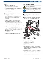
Fig. 5:
PC connections
1 Serial interface RS232
2)
2 Monitor connection (analog)
2)
3 RJ45 network connection
2)
4 USB ports for printer
1)
and DVD/CD drive
3)
5 Audio connections
2)
1)
Only printers approved by Bosch should be connected.
2)
Not used
3)
For connection see instruction manual 1 689 989 148
3.5.6
Flushing drain
When flushing DHK/UI, rotate the flushing drain (Fig. 3,
Pos. 5) downwards to stop the contaminated diesel/oil
mixture running into the test oil tank of the EPS 200.
For this purpose, a vessel must be placed under the
flushing drain on the workbench (on the left next to the
EPS 200).
3.5.7
Extraction controller for internal extractor
The internal extractor on the EPS 200 is automatically
activated when testing the jet pattern. It requires
compressed air to be connected on the rear of the unit
(Fig. 2, Pos. 1). The oil mist vapors that occur with
open injection are extracted from the jet chamber and
internally filtered. The extraction power is adjusted
using the extraction controller (Fig. 1, Pos. 8).
i
For the remaining oil mist, we also recommend
connecting an oil mist extraction and filter unit to the
external extraction connection (Fig. 1, Pos. 5).
3.5.8
Injection chamber, clamping ring, O-ring
Warning - Risk of burns
The hot surface of the injection chamber
can result in severe burns to the hands.
Wear protective gloves when removing
the injection chamber.
During the test, the CRI or DHK/UI injects the test oil
into the injection chamber. The test oil flows out of the
injection chamber through the hose line 1 680 712 287
back to the EPS 200 (DHK/UI flushing / test connection
or CRI/CRIN test connection, see Fig. 4).
458812-31
1
2
3
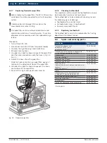
Fig. 6:
Injection chamber
1 Clamping ring (17 mm or 23 mm)
2 Clamping screw
3 Quick release coupling for flushing connection / test connection

