background image

-34-

4.

Problems in practical connection

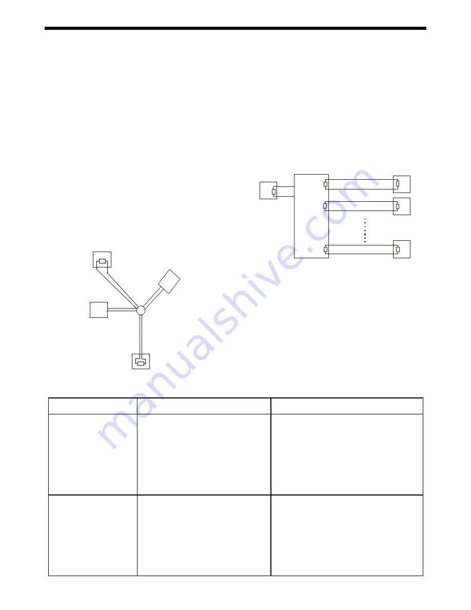
In some circumstances user adopts a star configu-

ration in practical connection. The termination re-

sistors must be connected to the two equipment

that are farthest away from each other, such as

equipment 1# and 15# in the Picture as below. As

the star configuration is not in conformity with the

requirements of RS485 standards, problems such

as signal reflections, lower anti-interference perfor-

mance arise when the cables are long in the

connection. The reliability of control signals is de-

creased with the phenomena that the system does

not respond to or just responds at intervals to the

controller, or does continuous operation without stop

( refer to the following picture).

6

M

a

in

C

o

ntr

oll

er

15#

1#

32#

5. RS485 Bus Troubleshooting ( refer to following form )

In such circumstances the factory recommends the

usage of RS485 distributor. The distributor can change

the star configuration connection to the mode of con-

nection stipulated in the RS485 standards. The new

connection achieves reliable data transmission (refer to

following picture).

Trouble

Possible Cause

Solution

The systemcan do self-
testing but cannot be
controlled

1. The address and baud rate settings of

system ars not in conformity with those
of controller

2. The"+"and "-"connection of RS485 Bus

is incorrect

3. Wiring is not fully seated
4. There is breakage in the middle section

of the RS485 Bus

1. Change the address and baud rate of controller

or system

2. Correct the connection

3. Make sure the connections are fully seated

The systemcan be
controlled
but the operation is not
smooth

1. The RS485 Bus line is not in good

contact with the connectors

2. One wire of the RS485 Bus is broken
3. The system is very far away from

controller

4. There are too many systems connected in

the system

1. Secure the connection

2. Replace RS485 Bus wires
3. Add termination resistors to the system

4. Install RS485 distributor

120

120

120

DR-HB16

Ma in
Controller

1 #

2#

A +

B -

16 #

Содержание BC2002-AT88

Страница 1: ...User Manual Before use the product please read this manual carefully BC2002 AT88 Integrated Positioning System BOLIDE R ...

Страница 2: ... Tree 10 Menu Operation 11 Operation Instruction 11 1 System Setup 12 2 Lens Parameters 17 3 Camera Parameters 18 4 Pan Tilt Parameters 20 5 Function Setting 22 6 Privacy Masking 27 Appendix I DIP Switch Jumper Settings 28 Appendix II RS485 Bus Basic Knowledge 33 Appendix III Lightning Proof Surge Proof 35 Appendix Trouble Shooting 36 ...

Страница 3: ... million times 77 to 40 tilt With RS485 Manchester Bi phase or Coaxitron control interfaces support Factory VCL PELCO P PELCO D PELCO C PHILIPS VICON KALATEL AMERICAN DYNAMICS MOLYNX PANASONIC etc protocols Up to 8 privacy masks Color Mono auto manual or switch at a set time for day night models With 4000V video data power lightning proof and surge proof Fit for the atrocious outdoor environment w...

Страница 4: ...d the user s authority to operate the equipment under CE and FCC rules Precautions 1 Only qualified and experienced person can carry on this installation 2 Always conform to national and local safety codes during installation 3 Use reliable tools only poor quality tools may cause danger e g ladder 4 Check the space and toughness of the site before installing It should be able to bear 4 times the w...

Страница 5: ...nkinds ofinstallationare available for intergatedpositioning system 1 Wall Mount 2 Corner Mount 3 Pole Mount 4 Pedestal Mount NOTE Installation site should be able to bear at least 4 times the weight of the positioning system 2 Corner Mount 1 Wall Mount 3 Pole Mount 4 Pedestal Mount ...

Страница 6: ...pter to the 4 M8 screws on bracket route the power cable and video cable through the cable hole and tighten the 4 M8 flat washers spring washers and nuts The last step is to route wires and cables through the centre ofthe mount bracket and close the cover NOTE it is recommended that two persons will carry out the installation for the sake of safety 5 Turnonthepower Ifself testing isnot carriedout ...

Страница 7: ... screw and uncap the covering ofthe mount 4 Aim the 4 holes on bracket adapter to the 4 M8 screws on bracket route the power cable and video cable through the cable hole and tighten the 4 M8 flat washers spring washers and nuts The last step is to route wires and cables through the centre ofthe mount bracket and close the cover NOTE it is recommended that two persons should carry out the installat...

Страница 8: ...ofthe mount 4 Aim the 4 holes on bracket adapter to the 4 M8 screws on bracket route the power cable and video cable through the cable hole and tighten the 4 M8 flat washers spring washers and nuts The last step is to route wires and cables through the centre ofthe mount bracket and close the cover NOTE it is recommended that two persons will carry out the installation for the sake of safety 5 Tur...

Страница 9: ...rriedout please refertoTroubleshooting 1 Put the pedestalmount ona solid aclinic ground aim the 4 holesonbracketadapter tothe 4M8screwsonthe flange route the power cable and video cable through the cable hole and tightenthe 4 M8 flat washers spring washers and nuts The last step is to route wires and cables through the centre ofthe pedestalmount 4 M8nut spring washer flat washer Power cable video ...

Страница 10: ... 8 Connections Connections for using RS 485 control RS 485 A B Monitor Video output Video input Video cable Power cable 24V ...

Страница 11: ...g coaxial control Connections OPEN CLOSE W IDE TELE NEAR FA R Monitor or video matrix Video input Video output Video cable Communication cable Power cable 24V Communication cable Video cable Power cable 24V Coaxial Convertor ...

Страница 12: ...eed High low 2 Max Digital Zoom Off 3 Focus Limit 1cm 4 Vibration Correction Off 5 Iris ALC Value 000 6 Iris PLC Value 000 7 Auto Recovery 8 Day Night Mode 9 Back 0 Exit Main Menu 1 System Setup 2 Lens Parameters 3 Camera Parameters 4 Pan Tilt Parameters 5 Function Setting 6 Privacy Masking 0 Exit System Setup 1 Device Information 2 Display Configuration 3 Change Password 4 Language Select 5 Facto...

Страница 13: ... cursor to the char acter you want to change and directly repeat step 4 Clear a character Switch the character to Symbol and then position the character you want to delete finally move the joystick up or down to select Blank Space character Editing the titles Up to 16 characters can be used for a title The fol lowing characters are avaiable A Z upper case a z lower case Symbol Ext Symbol w 0 9 num...

Страница 14: ...for the Enter S N setting 3 Move the joystick up or down to select the figure and move it to the left to save the setting 4 Move the joystick to the left or right to quit this editing 5 Select BACK to return to the previous menu Tip Move the joystick clockwise or anti clockwise to select upper case lower case and numeric input NOTE 1 If the S N is not identical with the original one the following ...

Страница 15: ...ys the region title for the region mode settings The following settings are available for each title OFF The title is not displayed when enabled ON The title is displayed after activation 2s 60s The title is displayed within a range of two seconds to sixty seconds after activation 1 2 2 Other Display 1 2 Display Configuration Main Menu System Setup Display Configuration Display Configuration 1 Tit...

Страница 16: ...s necessary to enter again in the same way otherwise you can not access to OSD menu Password change succeed Password not match Error Password 6 Set new password as the following submenu ap pears on the screen 7 Confirm the new password It is necessary to enter the new password again Enter New Password Input Back 5 If the old password is input wrongly the following picture is shown on the screen Th...

Страница 17: ...M Backlight Mode Off Iris ALCvalue 084 Backlight Value N A Iris PLCvalue 016 Auto Stop Timer Off Preset Freeze Off Speed Magnifier X01 Line Lock Phase Off Proportional PT ON Exposure Mode Auto Input Channel 1 Exposure Level N A AlarmAction Off Slow Shutter 1 1 5 Input Mode NO White Balance Auto AlarmLinkage Off Reset Delay Off AlarmOutput Off Factory Restoring 1 5 Factory Default Main menu System ...

Страница 18: ... Move the joystick to select ABOUT the following pic ture will display on the screen System S N 0000000000000000 System ID 0001 Hard Baudrate 4800 Protocol FACTORY Model BC2002 AT88 Camera temp 25C 77F P T temp 33C 91F Version f001 081015 Copy right 2003 2008 Any Command to Exit ...

Страница 19: ...value is illustrated as below 22X color camera 066 23X color mono camera 084 different camera has different ALC default value Note Changing default value is strongly NOT recommended 2 3 Focus Limit The focus limit sets the minimum distance between the object and the camera Focus is not achieved if the dis tance is less than the current setting The following values for focus limit are available 1cm...

Страница 20: ... AUTO 2 Exposure Level N A 3 Slow Shutter 1 1 5 4 Back 0 Exit To set exposure mode The value options are Auto Shutter Iris and AGC Shutter Set Shutter speed in priority values are 1 1 5 1 3 1 6 1 12 1 25 1 100 1 150 1 250 1 500 1 1000 1 2000 1 4000 1 10000 1 30000 Iris Set Iris in priority Values are F1 6 F2 2 F3 2 F4 4 F6 4 F8 8 F12 F17 F24 F34 Only one of settings for Shutter Iris and AGC will t...

Страница 21: ...fined R The value for the red setting increases the image appears more red User Defined B The value for the blue setting increases the image appears more blue OFF This function is disabled Normal Standard BLC mode WDR Wide Dynamic Range mode Note Only if White Balance is set to USER mode the value of User Defined R and User Defined B can be changed 3 4 White Balance This is used to manually adjust...

Страница 22: ...Preset N then select Preset N as correla tive Preset CorrelativeAUX 002 255 select the correlativeAUX When the system protocol is PELCO P D the correla tive AUX is 002 NOTE AUX 001 is for wiper control only Jet Dwell Time 000 255 Dwell time for jetting 000 means OFF 001 means 1second Return to Origin ON OFF return the camera back to the original place after jetting ON Enable the function OFF Disab...

Страница 23: ... 1 To Confirm 4 6 Set North Direction User can set the camera s orientation on screen by us ing joystick to position north Pan degree is the relative degree to a specific direction That direction is called NORTH Note Not restrict to geographical north Pan Origin Direction When it is ON it will check the original direction of observation When it is OFF it will take the current observation position ...

Страница 24: ...ch can be displayed on the screen Please refer to page 11 in details 3 Set New Preset This allows you to set the new preset The following picture will pop out as you tilt the joystick Move to the desired position and zoom to a suitable level call preset 1 to save the current preset call pre set 2 to cancel 4 Show Next Preset The next position is run accord ing to the numerical order 5 Delete Curre...

Страница 25: ...Select Save to save the sequence select Discard to quit without saving Note When a preset s dwell time is set 0 system will skip that preset System will consider pre set 0 as the end of a sequence Deleting Pattern Setup 1 Pattern Number 001 2 Title 0 3 Record New Pattern 4 Run Only Once 5 Run Continuously 6 Delete Current 7 Back 0 Exit 5 3 Pattern Setup Main Menu Function Setting Pattern setup A p...

Страница 26: ...n setup Autoscan Setup 1 Autoscan Number 001 2 Title 3 Set Left Limit 4 Set Right Limit 5 Defaul Speed 255 6 Run Continuously 7 Delete Current 8 Back 0 Exit This function allows you to set the left and right edges of the area to be monitored and the camera can move back and forth between these two points Up to four autoscan modes can be set The speed for autoscan can be set 1 Autoscan Number It se...

Страница 27: ...etween two sites User can edit a title for a REGION E g Dangerous area Whenever the camera moves into the region the title will display on the screen to alert the user Up to four regions can be set 1 Region Number It sets the autoscan mode number ranging from 001 to 004 2 Title It sets the name for the region which can be displayed on the screen Please refer to page 11 in details 3 Set Left Limit ...

Страница 28: ...on Autoscan 1 4 Enable Panning function NOTE The specified time can not be overlapped Otherwise the assigned Timer Running functions are ineffective Timer Running function is prior to Auto Action function Operations on keyboard will break the Timer Run ning function however the function will continue af ter 10 seconds idle time 5 7 Idle Action Main menu Function Setting Idle Action Idle Action 1 I...

Страница 29: ...ect SETUP NEW MASK from Main Menu 2 Move the joystick to the left or right The follow ing picture will display on the screen 3 Move the joystick to move the mask to the position to be masked and then call PRESET 1 to confirm call PRESET 2 to cancel The following picture will display on the screen Set width height Call preset 1 to confirm NOTE User should select other place or delete other mask pos...

Страница 30: ...he plug Protocol and Baud rate setting SW2 is used to set protocol and baud rate The first six 1 6 bits of SW2 are for protocol setting and the last two 7 8 bits are for baud rate setting Below chart shows the setting details O means ON blank means OFF Default setting is 4800 bps NOTE If you are using AD or PHILIPS or BBV protocol please set the baud rate to 19200 bps FACTORY VCL PELCO_P PELCO_D M...

Страница 31: ...he SW1 to 0 all OFF the system will react to any command for any ID NOTE Debug ID only works with Factory protocol Broadcast ID When a command is sent to broad cast ID all systems connected to the control bus will respond to that command Broadcast ID is definable ranges from 1 to 255 the default broad cast ID is 255 SW1 is used for seting dome ID The setting is strictly in accordance with binary s...

Страница 32: ... 30 O N ID Sw itc h N um b e r 1 2 3 4 5 6 7 8 O N ID Sw itc h N um b e r 1 2 3 4 5 6 7 8 ...

Страница 33: ...16 3 16 4 16 5 16 6 16 7 16 8 16 9 17 0 17 1 17 2 17 3 17 4 17 5 ID Sw itc h N um b e r 1 2 3 4 5 6 7 8 O N 17 6 17 7 17 8 17 9 18 0 18 1 18 2 18 3 18 4 18 5 18 6 18 7 18 8 18 9 19 0 19 1 19 2 19 3 19 4 19 5 19 6 19 7 19 8 19 9 20 0 20 1 20 2 20 3 20 4 20 5 20 6 20 7 20 8 20 9 21 0 21 1 21 2 21 3 21 4 21 5 21 6 21 7 21 8 21 9 ID Sw itch N um b e r 1 2 3 4 5 6 7 8 ...

Страница 34: ...ON 220 221 222 223 224 225 226 227 228 229 230 231 232 233 234 235 236 237 238 239 240 241 242 243 244 245 246 247 248 249 250 251 252 253 254 Switc h Number ID Progra m mab le Ad dress 255 1 2 3 4 5 6 7 8 ...

Страница 35: ... daisy chain con nection between the equipment There must be ter mination resistors with 120 Ohm impedance at both ends of the connection refer to following pictures Please refer to below picture for simple connection Distance D should not exceed 7 meters 3 2 The connection of 120 Ohm termination resistor The termination resistor is ready on the Protocol PCB There are two kinds of connection Pleas...

Страница 36: ... distributor can change the star configuration connection to the mode of con nection stipulated in the RS485 standards The new connection achieves reliable data transmission refer to following picture Trouble Possible Cause Solution The systemcan do self testing but cannot be controlled 1 The address and baud rate settings of systemars not in conformity with those of controller 2 The and connectio...

Страница 37: ...ation extra strong light ning proof equipment must be installed Take the building lightning proof requirements into ac count to design the lightning proof and grounding of outdoor equipment and cable laying out in accordance with the national and industrial standards The system must be grounded with equal potentials The earth ground connection must satisfy the anti interference and electrical safe...

Страница 38: ...n 4 Check the municipal power supply The red LED on the connection board is lit 1 The main controlling board is malfunction 2 Please contact the supplier for replacement of the main controlling board 1 Reset the DIP switchs according to the DIP switch setting chart 2 Check the connection of controlling cables in order to ensure they are in good condition 1 Operate the unit or call any preset 2 Cle...

Отзывы: