background image

Service Procedures 

26 

Blue Seal Evolution Series GT45 / GT46 / GT60                                                                                    

© 

Moffat Ltd, January 2007 

Revision 1/ 

Note:  

Ensure gas is isolated at main supply be-

fore any alterations are carried out on main 
gas controls. 

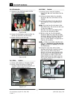
1)  Remove control panel (refer 6.1.1).   
2) Disconnect thermocouples, thermopile and 

thermostat leads, and pilot supply from gas 
control(s).   

3) Undo main injector supply line at bottom of 

gas control then undo gas control supply pipe 

from the top of the unit. Main gas control  
assembly can now be removed after removing 
2 securing screws fixing assembly to side 
panel inner flanges. 

4) Replace gas control in assembly. 
5) Refit by reversing above procedure. 

Note:

  Ensure gas thread connections are re-

sealed and electrical connections secured 

when servicing. 

6) Adjust pressure and pilot size as per 6.3.1 

and 6.3.3.  

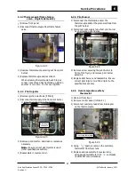
Figure 6.2.11 

6.2.11 Gas control  

(Twin tank models) 

6.2.10 Gas control  

(Single tank models) 

Note:  

Ensure gas is isolated at main supply be-

fore any alterations are carried out on main 

gas controls. 

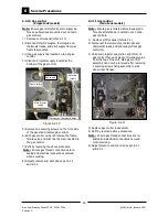
1)  Remove control panel (refer 6.1.1).   
2) Disconnect thermocouples, thermopile and 

thermostat leads, and pilot supply from gas 

flame failure valve.   

3) Undo gas supply line located on top of gas 

control. 

4) Undo main injector supply located at the  

bottom of the gas control. 

Figure 6.2.10 

Flame failure 

Main injector 

supply  

5) Remove two securing screws on the front side 

of the panel and remove gas control. 

6) With gas control on bench remove the flame 

failure valve and pilot line that is connected to 
the gas control. 

7) Refit by reversing the above procedure. 
 

Note:

  Ensure gas thread connections are re-

sealed and electrical connections secured 
when servicing. 

8) Adjust pressure and pilot size as per 6.3.1 

and 6.3.3. 


Securing 

screws 

Gas supply 

Thermostat / thermopile leads 

Содержание Evolution GT45

Страница 1: ...1 Blue Seal Evolution Series GT45 GT46 GT60 Moffat Ltd January 2007 Revision 1 Service Manual Gas Fryers GT45 GT46 GT60 ...

Страница 2: ...tion Series GT45 GT46 GT60 Moffat Ltd January 2007 Revision 1 ALL INSTALLATION AND SERVICE REPAIR WORK MUST BE CARRIED OUT BY QUALIFIED PERSONS ONLY WARNING MAKING ALTERATIONS MAY VOID WARRANTIES AND APPROVALS IMPORTANT ...

Страница 3: ... this manual gives a full explanation as to how and what effects will result Section Page Number 1 Specifications 1 2 Installation 5 3 Operation 9 3 1 Description of Controls 3 2 Explanation of Control System Single Tank Fryers 3 3 Explanation of Control System Twin Tank Fryers 4 Cleaning and Maintenance 13 5 Trouble shooting Guide 15 5 1 Trouble shooting Chart 5 2 Fault Diagnosis 6 Service Proced...

Страница 4: ...4 Blue Seal Evolution Series GT45 GT46 GT60 Moffat Ltd January 2007 Revision 1 ...

Страница 5: ...1 1 Specifications Blue Seal Evolution Series GT45 GT46 GT60 Moffat Ltd January 2007 Revision 1 External dimensions GT45 Dimensions shown in millimetres Legend Gas connection entry point BSP male ...

Страница 6: ...1 Specifications 2 Blue Seal Evolution Series GT45 GT46 GT60 Moffat Ltd January 2007 Revision 1 External dimensions GT46 Dimensions shown in millimetres Legend Gas connection entry point BSP male ...

Страница 7: ...3 1 Specifications Blue Seal Evolution Series GT45 GT46 GT60 Moffat Ltd January 2007 Revision 1 External dimensions GT60 legend Gas connection entry point BSP male Dimensions shown in millimetres ...

Страница 8: ...m 0mm Right hand side 50mm 0mm Top 610mm 610mm Front 600mm 600mm Top clearance is from flue outlet to any above surface Front clearance is in order to facilitate easy operation drainage and servicing of the appliance Installation clearances Tank capacity Injector sizes Natural Gas LP Gas Propane Input Rating 90 MJ hr 90 MJ hr N H G C 85 300 Btu hr 85 300 Btu hr Supply Pressure 1 13 2 00 kPa 2 75 3...

Страница 9: ...ons only Failure to install equipment to the relevant codes and manufacturer s specifications shown in this section will void the warranty Components having adjustments protected e g paint sealed by manufacturer are only allowed to be adjusted by an authorised service agent They are not to be adjusted by the installation person Unpacking Remove all packaging and transit protection from the applian...

Страница 10: ...be carried out on completion of the gas connection Refer to the Gas Connection section below Optional Accessories Refer to Replacement Parts List Plinth Kit For installation details refer to the instructions supplied with each kit Gas Connection NOTE ALL GAS FITTING MUST ONLY BE CARRIED OUT BY A QUALIFIED SERVICE PERSON 1 Blue Seal Fryers do not require an electrical connection they function total...

Страница 11: ...ing the regulator screw of the gas control valve as shown in the Gas Conversion and Specifications section 7 Check all gas connections for leakages using soapy water or other gas detecting equipment NOTE The operating pressure is to be measured at the upper test point Supply Pressure on the gas control valve located behind the access door and through the access hole in the control panel this is to...

Страница 12: ...o Filling the Tank in the Operation Section of the Manual and setting the thermostat to 180 C Light the pilot burners and turn on the main burners in accordance with Operation Instructions found in the User manual c The calibration of the thermostat should be checked once the oil is up to temperature If a discrepancy is found the thermostat calibration should be referred to the supplier d Ensure t...

Страница 13: ...Tank GT46 Controls 3 1 Description of controls Single Tank GT45 Controls Flame Failure Button Piezo Igniter Gas Control Valve Thermostat Control Knob Piezo Igniter Gas Control Valve Flame Failure Button Thermostat Control Knob Thermostat Control Knobs for each Tank Piezo Ignitor Gas Control Valve ...

Страница 14: ...3 Operation 10 Blue Seal Evolution Series GT45 GT46 GT60 Moffat Ltd January 2007 Revision 1 Piezo Igniters Gas Control Valve Thermostat Control Knob Flame Failure Button Single Tank GT60 Controls ...

Страница 15: ...alight If the pilot burners do not ignite repeat Items 1 to 9 above GT46 Fryer Twin Tank 1 With the fryer tank full of frying medium the pilot burners can be lit 2 Check that the gas supply is turned on at the mains supply 3 Open the access door at the front of the ap pliance to access the control panel 4 Rotate the right hand gas control knob to the position marked PILOT and hold depressed 5 Depr...

Страница 16: ...leshooting Guide section 5 should be used to identify any incorrect fryer operation On correct identification of the fault the Trouble shooting Guide will make reference to the corrective action required or refer to the Fault Diagnosis section and or Service section to assist in correction of the fault The gas control circuit in these fryers is operated by two millivolt circuits The first is the p...

Страница 17: ...e drained and strained into a receptacle b Use a drain stick if necessary to stir up any solid medium into the top medium to melt it Slip a muslin or other suitable bag over the drain valve Crumbs will be caught in the bag but frying medium will strain freely through bag into the receptacle When the tank is empty use a small tank with a handle as a ladle and dip into the hot frying medium from rec...

Страница 18: ...imately 80 90 C d Clean the fryer baskets at the same time by simply immersing them in the cleaning solution Allow the fryer to soak for 5 10 minutes or as directed on the cleaner instructions Remove the baskets and turn OFF the main burners e Scrub the baskets and fryer tank lightly but vigorously with a stiff nylon bristle brush to remove any remaining deposits DO NOT use a wire brush as this wi...

Страница 19: ...r service section 6 3 10 6 2 11 Replace flame failure valve Refer to section 6 2 15 Clean or replace pilot spud Refer service section 6 2 3 Pilot goes out when knob released Releasing knob before the thermocouple heated Pilot flame too small Refer fault Pilot Flame small Thermocouple faulty Refer fault diagnosis 5 2 1 Over temperature thermostat faulty Refer fault diagnosis 5 2 1 Gas control valve...

Страница 20: ...owing pilot out Thermocouple faulty Refer fault diagnosis 5 2 1 Over temp thermostat faulty Refer fault diagnosis 5 2 1 Main gas control valve faulty Flame failure valve faulty GT45 and GT60 only Check supply adjust pressure Shield fryer from excessive breeze Replace thermocouple Refer service section 6 2 1 6 2 2 Replace Refer service section 6 2 5 Replace gas contro0l magnet Replace flame failure...

Страница 21: ... pilot flame Refer fault Small pilot flame Gas control faulty Thermostat out of calibration Placing food into oil too soon Too large a load Supply correct pressure Replace thermopile refer service section 6 2 6 Correct fault Replace gas control Refer service section 6 2 10 6 2 11 Recalibrate thermostat Refer service section 6 3 2 Give the fryer more time to come up to temperature before inserting ...

Страница 22: ...ermocouple from the rear of the flame failure valve Ignite the pilots and while still holding the flame failure blue pilot button in measure the voltage between the removed end of the thermocouple and earth The reading should be approximately 30mV If the reading is less than 10mV and there is satisfactory flame impingement on the thermo Figure 5 2 1a couple the thermocouple is faulty replace If th...

Страница 23: ...e used for manual back up ignition Overtemp tripped Check the oil temp with the thermometer If the oil temperature has reached over 220 C the overtemp should have tripped open circuit and will not reset until the temperature has dropped below 192 C If the oil temperature is below 180 C and the overtemp is still open circuit then the overtemp is faulty Overtemp faulty To check if the overtemp is fa...

Страница 24: ...tion If there is still no continuity then replace the thermostat If there is continuity through the thermostat connection then set gas control knob to main flame position Check millivolts generated by the thermopile across terminals TP and TH middle and RH connection A minimum of 150mV is required to hold gas valve open If a greater value than this is obtained but the main burner will not come on ...

Страница 25: ... Thermocouple Gas Control 22 6 2 2 Thermocouple Flame Failure Valve Single Tank Models 23 6 2 3 Pilot Injector 23 6 2 4 Pilot Burner 23 6 2 5 Over temperature Safety Thermostat 23 6 2 6 Thermostat 24 6 2 7 Main Burner Injector 24 6 2 8 Main Burner 24 6 2 9 Thermostat 25 6 2 10 Gas Control Valve Single Tank Models 26 6 2 11 Gas Control Valve Twin Tank Models 26 6 2 12 Piezo Ignitor 27 6 2 13 Piezo ...

Страница 26: ...gure 6 2 1b 1 Disconnect thermocouple from gas control 2 Unscrew the overtemp thermostat wires from the connector block on the thermocouple 3 Unscrew thermocouple securing nut from pilot burner Note It may be necessary to remove the piezo ignition electrode from the pilot assembly before removing thermocouple 4 Replace thermocouple and reconnect When screwing thermocouple back into gas control onc...

Страница 27: ... nut from pilot burner 4 Replace thermocouple and reconnect When screwing thermocouple back into gas control once thread has tightened up tighten another turn only Do not over tighten 3 Remove pilot injector and clean or replace as necessary Note Ensure correct size injector is used refer specifications section 4 Reassemble in reverse order 1 Drain oil from fryer 2 Remove control panel refer 6 2 1...

Страница 28: ... be no shiny stainless steel of the tank ex posed or white substance if required and re move any loose coating NOTE If touch up or recoat is required use a spray can of matt black high temperature enamel VHT1200 or equivalent to re coat the affected area 5 Holding the new burner with one hand underside and the other holding the throat push up the rear of the burner until it positions on the rear s...

Страница 29: ...at refer 6 3 2 Note On twin tank models both thermostat knobs will need to be removed Thermostat leads Figure 6 2 8b 6 2 9 Thermostat 1 Drain oil from fryer 2 Remove control panel refer 6 1 1 3 Remove the overtemp thermostat refer 6 3 4 4 Disconnect thermostat leads from gas control terminal block 6 Once the rear is supported the front can be pushed up into its location The small notch in each sid...

Страница 30: ...ize as per 6 3 1 and 6 3 3 Figure 6 2 11 6 2 11 Gas control Twin tank models 6 2 10 Gas control Single tank models Note Ensure gas is isolated at main supply be fore any alterations are carried out on main gas controls 1 Remove control panel refer 6 1 1 2 Disconnect thermocouples thermopile and thermostat leads and pilot supply from gas flame failure valve 3 Undo gas supply line located on top of ...

Страница 31: ...piezo electrode replace and reassemble in reverse order 6 2 12 Piezo ignitor 6 2 13 Piezo Electrode 6 2 14 High tension lead Figure 6 2 14 Piezo electrode nut Figure 6 2 12 Piezo 1 Remove control panel refer 6 1 1 2 Remove thermocouple gas inlet and outlet pipes 3 Undo bracket securing nut 6 2 15 Flame failure valve Thermocouple Gas supply line Gas Outlet line Securing Nut 4 Remove flame failure v...

Страница 32: ...s reached 3 Turn thermostat shaft until cycling on off point reached Check oil temperature and find point at which rotating shaft back and forth slightly will cause burners to cycle on off 4 Recheck oil temperature should be between 150 C and 190 C and refit control knob with pointer at temperature setting on control panel that reflects actual oil temperature Allow fryer to cycle and make any fine...

Страница 33: ...ffat Ltd January 2007 Revision 1 Side splash panel LH Part no 228898 RH Part no 228899 Joining strip Part no 228600 Drain extension kit Part no 024710 Drain adaptor Part no 024705 Side splash panel joiner for griddle chargrill LH Part no 228894 RH Part no 228895 ...

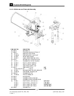
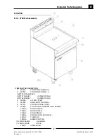
Страница 34: ...228770 SPLASHBACK 450 BS 4 227441 BASKET HANGER 370mm 5 228761 LID 450 FRYER 6 227762 HOB FRONT WA BSEAL 7 227696 CONTROL PANEL GT45 46 8 230422 FRYER DOOR ASSEMBLY NO BADGE 227449 DOOR HANDLE 228846 DOOR OUTER 227453 DOOR INNER 227466 FRYER CATCH RECEIVER 228132 TUBE CLIP 228308 HINGE PIVOT WA 9 227960 BADGE BLUESEAL 10 228300 HINGE PLATE 228301 HINGE BUSH 8 1 GT45 8 1 1 GT45 Main Assembly ...

Страница 35: ...18019 FRYER BASKET STANDARD 12 228576 BASKET TRAY 450mm 1 PAN GAS 13 228127 FISH PLATE GT45 14 227856 MAGNETIC CATCH 02 10 201 10 15 018358 BALL VALVE 16 227852 LEG PLATE 17 227850 LEG 150mm FLUSH STUD 18 229674 REAR ROLLER ASSY 19 229671 LEG RING PLATE THREADED ITEM PART NO DESCRIPTION 8 1 2 GT45 Main Assembly ...

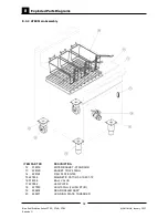
Страница 36: ... KIT 23 019237 FLAME FAILURE VALVE M1A HP 24 227508 PIEZO IGNITOR M18 25 032310 INJECTOR 3 10mm NAT 032190 INJECTOR 1 90mm LPG PROPANE 26 227636 INJECTOR SUPPLY TUBE 27 227638 SUPPLY TUBE 28 227639 PILOT SUPPLY TUBE 29 227131 MANIFOLD 450 FRYER 30 020628 TEE 3 8 COMPRESSION 31 018111 TEE 64x4 TITON FITTING 32 227779 PILOT TUBE 33 229511 INJECTOR ELBOW x3 8T 34 227694 BURNER INJECTOR MTG BRACKET IT...

Страница 37: ...OL GT45 38 018145 KNOB 8010 A SPECIAL BLACK 39 018171 THERMOSTAT STOP PLATED 40 018094 THERMOCOUPLE INTERRUPTED 41 227865 THERMOCOUPLE 850mm M8 42 018090K PILOT BURNER KIT 43 018744 ELECTRODE 44 018743 THERMOCOUPLE SPACER 45 018091 PILOT SPUD NAT 0 62mm NAT ONLY 018092 PILOT SPUD LPG 0 35mm LPG ONLY 018972 PILOT INJECTOR 0 45mm UK NAT ONLY 018971 PILOT INJECTOR 0 30mm UK PROPANE ONLY 46 018093 THE...

Страница 38: ...228770 SPLASHBACK 450 BS 4 227441 BASKET HANGER 370mm 5 228761 LID 450 FRYER 6 227762 HOB FRONT WA BSEAL 7 227696 CONTROL PANEL GT45 46 8 230422 FRYER DOOR ASSEMBLY NO BADGE 227449 DOOR HANDLE 228846 DOOR OUTER 227453 DOOR INNER 227466 FRYER CATCH RECEIVER 228132 TUBE CLIP 228308 HINGE PIVOT WA 9 227960 BADGE BLUESEAL 10 228300 HINGE PLATE 228301 HINGE BUSH 8 2 GT46 8 2 1 GT46 Main Assembly ...

Страница 39: ...2 GT46 Main Assembly ITEM PART NO DESCRIPTION 11 018019 FRYER BASKET STANDARD 12 228577 BASKET TRAY 450mm 2 PAN GAS 13 228565 FISH PLATE GT46 14 227856 MAGNETIC CATCH 02 10 201 10 15 018358 BALL VALVE 16 227852 LEG PLATE 17 227850 LEG 150mm FLUSH STUD 18 229674 REAR ROLLER ASSY 19 229671 LEG RING PLATE THREADED ...

Страница 40: ...D 28 227649 PILOT SUPPLY TUBE RH 29 227647 PILOT SUPPLY TUBE LH 30 229511 INJECTOR ELBOW x3 8T 31 032310 INJECTOR 3 10mm NAT 032190 INJECTOR 1 90mm LPG 32 227694 BURNER INJECTOR MTG BRACKET 33 018022K OVERTEMP CONTROL KIT 34 018021K THERMOSTAT KIT 35 018090K PILOT BURNER KIT 36 018744 ELECTRODE 37 018743 THERMOCOUPLE SPACER 38 018094 THERMOCOUPLE INTERRUPTED 39 018091 PILOT SPUD NAT 0 62mm NAT ONL...

Страница 41: ...SHBACK 4 227747 BASKET HANGER 305mm 5 227748 BASKET HANGER 195mm 6 228762 LID 600 FRYER 7 227903 HOB FRONT WA BSEAL 8 227701 CONTROL PANEL GT60 9 230424 FRYER DOOR ASSEMBLY NO BADGE 227459 DOOR HANDLE 228847 DOOR OUTER 227462 DOOR INNER 227466 FRYER CATCH RECEIVER 228132 TUBE CLIP 228308 HINGE PIVOT WA 10 227960 BADGE BLUESEAL 11 228300 HINGE PLATE 228301 HINGE BUSH 8 3 GT60 8 3 1 GT60 Main Assemb...

Страница 42: ... 8 3 2 GT60 Main Assembly 12 018019 FRYER BASKET STANDARD 13 228129 BASKET TRAY 600mm 14 228128 FISH PLATE GT60 15 227856 MAGNETIC CATCH 02 10 201 10 16 018358 BALL VALVE 17 227852 LEG PLATE 18 227850 LEG 150mm FLUSH STUD 19 229674 REAR ROLLER ASSY 20 229671 LEG RING PLATE THREADED ITEM PART NO DESCRIPTION ...

Страница 43: ...ILLIVOLT VALVE KIT 24 019237 FLAME FAILURE VALVE M1A HP 25 227508 PIEZO IGNITOR M18 26 032310 INJECTOR 3 10mm NAT 032190 INJECTOR 1 90mm LPG 27 227654 INJECTOR SUPPLY TUBE 28 227655 SUPPLY TUBE 29 227760 PILOT SUPPLY TUBE 30 227134 MANIFOLD 600 FRYER 31 023816 BALL VALVE 1 2 BSP M F TEE 32 020628 TEE 3 8 COMPRESSION 33 018111 TEE 64x4 TITON FITTING 34 227780 PILOT TUBE 35 229511 INJECTOR ELBOW x3 ...

Страница 44: ...ACK 41 018171 THERMOSTAT STOP PLATED 42 018094 THERMOCOUPLE INTERRUPTED 43 227865 THERMOCOUPLE 850mm M8 44 018090K PILOT BURNER KIT 45 018744 ELECTRODE 46 018743 THERMOCOUPLE SPACER 47 018091 PILOT SPUD NAT 0 62mm NAT ONLY 018092 PILOT SPUD LPG 0 35mm LPG ONLY 018972 PILOT INJECTOR 0 45mm UK NAT ONLY 018971 PILOT INJECTOR 0 30mm UK PROPANE ONLY 48 018093 THERMOPILE ITEM PART NO DESCIPTION 8 3 4 GT...

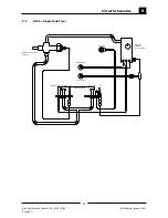
Страница 45: ...on Series GT45 GT46 GT60 Moffat Ltd January 2007 Revision 1 9 1 GT45 Single Tank Fryer TP TH THERMOSTAT OVER TEMP TH TP IGNITION THERMOPILE L H PILOT T C R H PILOT CROSS LIGHTING T C FLAME FAILURE VALVE SIT M1 A MAIN GAS CONTROL SIT NOVA 820mV ...

Страница 46: ...ution Series GT45 GT46 GT60 Moffat Ltd January 2007 Revision 1 9 2 GT60 Single Tank Fryer THERMOPILE IGNITION TP TH OVER TEMP THERMOSTAT TH TP MAIN GAS CONTROL SIT NOVA 820mV FLAME FAILURE VALVE SIT M1 A T C IGNITION R H PILOT T C L H PILOT ...

Страница 47: ... GT45 GT46 GT60 Moffat Ltd January 2007 Revision 1 9 3 GT46 Fryer Twin Tank Fryer TH TP TH TP MAIN GAS CONTROL SIT NOVA 820mV MAIN GAS CONTROL SIT NOVA 820mV PILOT PILOT T C THERMOPILE TC THERMOPILE IGNITION IGNITION TP TH TH TP OVER TEMPS THERMOSTATS ...

Страница 48: ...OUTH AUSTRALIA MOFFAT PTY 28 Greenhill Rd Tel 08 8274 2116 Wayville SA 5034 Spare Parts Free Call 1800 337 963 Fax 03 9518 3895 WESTERN AUSTRALIA MOFFAT PTY PO Box 689 Tel 08 9305 8855 Joondalup Business Centre WA 6027 Spare Parts Free Call 1800 337 963 Fax 03 9518 3895 NATIONAL COVERAGE FOR 24 HOUR SERVICE OR MAINTENANCE DIAL FREE CALL 1800 622 216 AUSTRALIA ONLY Canada SERVE CANADA 22 Ashwarren ...

Страница 49: ...10 Service Contacts 45 Blue Seal Evolution Series GT45 GT46 GT60 Moffat Ltd January 2007 Revision 1 United Kingdom Utensils Direct 0845 873 6600 www utensilsdirect co uk ...

Страница 50: ...termine the correct injectors for the corresponding gas from the Gas Specifications Table at the end of this section 3 Screw in the correct sized injectors Refer to the Gas Specifications Table at the end of this section Pilot Burner Injectors 1 Unscrew the pilot supply tube from the pilot burner fitted to the mounting bracket and remove the pilot injector NOTE On appliances fitted with piezo igni...

Страница 51: ... adjust the main burner controlled by the second gas control valve Pilot Burner Flame Adjustment a Once the main burner operating pressure has been set the pilot burner supply can be adjusted so that impingement of the pilot flame on the thermocouple and thermopile is correct and the main burner pilot flame ignites the main burners satisfactorily b Adjust the pilot flame size by adjusting the pilo...

Страница 52: ...ectly NOTE If for some reason it is not possible to get the appliance to operate correctly shut off the gas supply and contact the supplier of this appliance Gas Specifications NOTE The burner operating pressure is to be measured at the upper test point Supply Pressure on the gas control valve located behind the access door and through the access hole in the control panel this is to be carried out...

Страница 53: ...49 Blue Seal Evolution Series GT45 GT46 GT60 Moffat Ltd January 2007 Revision 1 ...

Отзывы: