


9-3. Lift Cylinder (Telescopic)
9-3.1. Removal
1.
With the lift truck wheels securely blocked, raise
the forks approximately three feet from floor and
position blocks or strong supports under inner
mast
2.
Lower inner mast onto the support. Check that
arrangement is secure before proceeding.
3.
Turn off the key switch (6,
) and dis-
connect the batteries.
WARNING: Before attempting any replacement,
make certain power is disconnected.
4.
Remove screw (9,
), lock washer (10)
and flat washer (11).
5.
Remove screw (28).
CAUTION:
Hydraulic oil can damage parts. Wipe off
any oil immediately. Provide a container
under the line or fitting before discon-
necting.
6.
Loosen hose (1,
) at the bottom of lift
cylinder and manually push the cylinder rod down
as far as possible. The chains will become slack
and need not be removed.
7.
Disconnect the hose from the bottom of lift cylin-
der.
8.
Lift chains clear of sheaves (13,
) and
lay them aside.
WARNING: Support lift cylinder before performing
the following steps to prevent cylinder
from falling.
9.
Tilt lift cylinder (17) and ram head (14) forward
from their position in the truck.
10. Lift ram head from the cylinder.
11. Raise lift cylinder assembly up and out of truck.
9-3.2. Repair
CAUTION:
To prevent damage, use proper pipe
clamp vise. The cylinder will be distorted
if the vise is tightened too much.
1.
Secure the lift cylinder in a vise, clamping lightly
at the base of the cylinder.
2.
Remove gland nut (7,
).
3.
Remove wiper ring (8) and O-ring (9) from gland
nut (7).
4.
Pull out piston rod (1).
5.
Remove bushing (4) and bearing (5)
6.
Remove piston (2) and O-ring (3) from rod (1).
7.
Remove packing (11) and backup ring (10) from
piston (1).
8.
Coat all parts with hydraulic oil (
9.
Install packing (11) and backup ring (10) on piston
(1).
10. Install new O-ring (3) on rod (1).
11. Install piston (2) on rod (1).
12. Install bushing (4) and bearing (5)
13. Insert rod (1) in cylinder tube (6).
14. Install wiper ring (8) and O-ring (9) on gland nut
(7).
15. Install gland nut (7) in cylinder tube (1).
9-3.3. Installation
1.
Position the cylinder on outer mast (18,
).
2.
With the cylinder tilted slightly forward, position
ram head (14) on top of cylinder (17). Then tilt the
cylinder back into position.
3.
Lift up the lift chains and position them on
sheaves (13).
4.
Using a suitable lifting device, lift the inner mast
and remove the supports.
5.
Slowly lower the inner mast while lining up the lift
cylinder with positioner (12).
6.
Secure the top of the cylinder with screw (9), lock
washer (10) and flat washer (11).
7.
Secure the bottom of the cylinder with screw (28).
8.
Reconnect the hose (1,
) to the bottom
of lift cylinder.
9.
Adjust the chains according to paragraph
10. Fill the hydraulic reservoir. Use hydraulic oil listed
in
.
11. Reconnect the batteries and turn on the keyswitch
(6,
12. Operate the lift and lower buttons to refill the
cylinder and lines with hydraulic oil.
13. Check level of hydraulic oil. If required, add
hydraulic oil to bring to proper level. Use hydraulic
oil listed in
57
Содержание BGL-22
Страница 12: ...NOTES 12...
Страница 18: ...NOTES 18...
Страница 34: ...NOTES 34...
Страница 39: ...Figure 5 4 Cap Assembly R6878 39...
Страница 42: ...Figure 6 1 Transmission Motor Brake Assembly R6879 42...
Страница 44: ...Figure 7 1 Transmission Motor Brake Assembly R6879 44...
Страница 45: ...Figure 7 2 Load Wheels R6882 45...
Страница 46: ...NOTES 46...
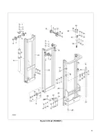
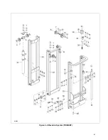
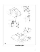
Страница 48: ...Figure 8 2 Elevation System Telescopic R6883 48...
Страница 50: ...Figure 8 3 Mast TRIMAST R6884 50...
Страница 52: ...NOTES 52...
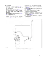
Страница 54: ...Figure 9 1 Hydraulic System R6886 54...
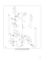
Страница 56: ...Figure 9 3 Hydraulic System TRIMAST R6888 56...
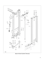
Страница 58: ...Figure 9 4 Elevation System Telescopic R6883 58...
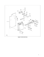
Страница 59: ...Figure 9 5 Lift Cylinder Telescopic R6889 59...
Страница 61: ...Figure 9 6 Elevation System TRIMAST R6884 61...
Страница 62: ...Figure 9 7 Free Lift Cylinder TRIMAST R6890 62...
Страница 64: ...Figure 9 8 Secondary Lift Cylinder TRIMAST R6891 64...
Страница 67: ...Figure 9 10 Tilt Cylinder R6893 67...
Страница 68: ...NOTES 68...
Страница 70: ...Figure 10 1 Electrical System R6478 R6894 70...
Страница 71: ...Figure 10 2 Electrical Panel R6478 R6895 71...
Страница 73: ...Figure 10 3 Transmission Motor Brake Assembly R6879 73...
Страница 74: ...NOTES 74...
Страница 75: ...SECTION 11 OPTIONAL EQUIPMENT 75...
Страница 76: ...NOTES 76...
Страница 78: ...Figure 12 1 Steering System R6876 78...
Страница 80: ...Figure 12 2 Control Head R6877 80...
Страница 82: ...Figure 12 3 Cap Assembly R6878 82...
Страница 85: ...NOTES 85...
Страница 86: ...Figure 12 5 Transmission Motor Brake Assembly R6879 86...
Страница 89: ...NOTES 89...
Страница 90: ...Figure 12 7 Frame R6881 90...
Страница 92: ...Figure 12 8 Load Wheels R6882 92...
Страница 94: ...Figure 12 9 Elevation System Telescopic R6883 94...
Страница 96: ...Figure 12 10 Elevation System TRIMAST R6884 96...
Страница 98: ...Figure 12 11 Lift Carriage R6815 98...
Страница 101: ...NOTES 101...
Страница 102: ...Figure 12 13 Hydraulic System R6665 102...
Страница 104: ...Figure 12 14 Pump Motor R6886 104...
Страница 107: ...NOTES 107...
Страница 108: ...Figure 12 16 Hydraulic System TRIMAST R6888 108...
Страница 110: ...Figure 12 17 Tilt Cylinder Mounting R6892 110...
Страница 112: ...Figure 12 18 Lift Cylinder Telescopic R6889 112...
Страница 114: ...Figure 12 19 Free Lift Cylinder TRIMAST R6890 114...
Страница 116: ...Figure 12 20 Secondary Lift Cylinder TRIMAST R6891 116...
Страница 118: ...Figure 12 21 Tilt Cylinder R6893 118...
Страница 120: ...Figure 12 22 Electrical System R6894 120...
Страница 123: ...NOTES 123...
Страница 124: ...Figure 12 24 Drive Motor R6630 124...
Страница 128: ...NOTES 128...
Страница 129: ...129...


