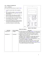
4-2.4.2. Adjustments
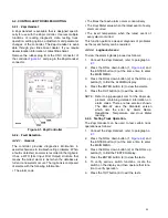
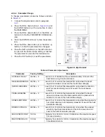
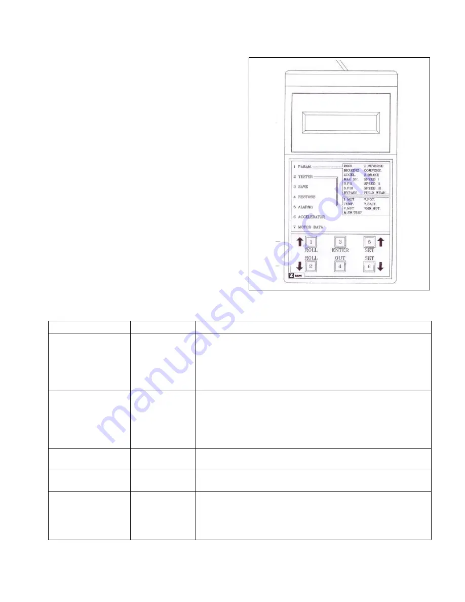
To change an adjustment proceed as follows and refer
to
1.
Connect the Zapi Handset, refer to paragraph
2.
Press the ROLL up button (1,
) and the
SET up button (5) at the same time to enter the
CONFIG MENU.
3.
Press the ROLL down button (1) or the ROLL up
button (2) to find the ADJUSTMENTS display.
4.
Press the ENTER button (3) to view the adjust-
ments.
5.
Press the ROLL down button (2) or the ROLL up
button (1) to find the adjustment to be changed.
6.
Press the SET up button (5) or the SET down but-
ton (6) until the desired value setting is reached.
The adjustment is now set at the desired value.
7.
Press the OUT button (4) to exit the adjustments.
Figure 4-3 Zapi Handset
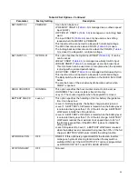
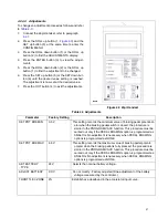
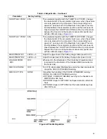
Table 4-3 Adjustments
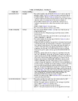
R6624
Parameter
Factory Setting
Description
SET POT BRK MIN
0.5 V
This setting records the minimum value of braking pedal potentiom-
eter when the braking pedal switch is closed; the procedure is
similar to the PROGRAM VACC function. This procedure must be
carried out only if the PEDAL BRAKING option is programmed as
ANALOG. No adjustment is necessary when PEDAL BRAKING
options is programmed as NONE.
SET POT BRK MAX
4.5 V
This setting records the maximum value of braking pedal potenti-
ometer when the braking pedal is fully pressed; the procedure is
similar to the PROGRAM VACC function. This procedure must be
carried out only if the PEDAL BRAKING option is programmed as
ANALOG. No adjustment is necessary when PEDAL BRAKING
options is programmed as NONE.
SET BATTERY
TYPE
24V
Selects the nominal battery voltage.
ADJUST BATTERY
XX V
Do not modify - Factory adjusted (Fine adjustment of the battery
voltage measured by the controller.)
THROTTLE 0 ZONE
9%
Establishes a deadband in the accelerator input curve.
27
Содержание BGL-22
Страница 12: ...NOTES 12...
Страница 18: ...NOTES 18...
Страница 34: ...NOTES 34...
Страница 39: ...Figure 5 4 Cap Assembly R6878 39...
Страница 42: ...Figure 6 1 Transmission Motor Brake Assembly R6879 42...
Страница 44: ...Figure 7 1 Transmission Motor Brake Assembly R6879 44...
Страница 45: ...Figure 7 2 Load Wheels R6882 45...
Страница 46: ...NOTES 46...
Страница 48: ...Figure 8 2 Elevation System Telescopic R6883 48...
Страница 50: ...Figure 8 3 Mast TRIMAST R6884 50...
Страница 52: ...NOTES 52...
Страница 54: ...Figure 9 1 Hydraulic System R6886 54...
Страница 56: ...Figure 9 3 Hydraulic System TRIMAST R6888 56...
Страница 58: ...Figure 9 4 Elevation System Telescopic R6883 58...
Страница 59: ...Figure 9 5 Lift Cylinder Telescopic R6889 59...
Страница 61: ...Figure 9 6 Elevation System TRIMAST R6884 61...
Страница 62: ...Figure 9 7 Free Lift Cylinder TRIMAST R6890 62...
Страница 64: ...Figure 9 8 Secondary Lift Cylinder TRIMAST R6891 64...
Страница 67: ...Figure 9 10 Tilt Cylinder R6893 67...
Страница 68: ...NOTES 68...
Страница 70: ...Figure 10 1 Electrical System R6478 R6894 70...
Страница 71: ...Figure 10 2 Electrical Panel R6478 R6895 71...
Страница 73: ...Figure 10 3 Transmission Motor Brake Assembly R6879 73...
Страница 74: ...NOTES 74...
Страница 75: ...SECTION 11 OPTIONAL EQUIPMENT 75...
Страница 76: ...NOTES 76...
Страница 78: ...Figure 12 1 Steering System R6876 78...
Страница 80: ...Figure 12 2 Control Head R6877 80...
Страница 82: ...Figure 12 3 Cap Assembly R6878 82...
Страница 85: ...NOTES 85...
Страница 86: ...Figure 12 5 Transmission Motor Brake Assembly R6879 86...
Страница 89: ...NOTES 89...
Страница 90: ...Figure 12 7 Frame R6881 90...
Страница 92: ...Figure 12 8 Load Wheels R6882 92...
Страница 94: ...Figure 12 9 Elevation System Telescopic R6883 94...
Страница 96: ...Figure 12 10 Elevation System TRIMAST R6884 96...
Страница 98: ...Figure 12 11 Lift Carriage R6815 98...
Страница 101: ...NOTES 101...
Страница 102: ...Figure 12 13 Hydraulic System R6665 102...
Страница 104: ...Figure 12 14 Pump Motor R6886 104...
Страница 107: ...NOTES 107...
Страница 108: ...Figure 12 16 Hydraulic System TRIMAST R6888 108...
Страница 110: ...Figure 12 17 Tilt Cylinder Mounting R6892 110...
Страница 112: ...Figure 12 18 Lift Cylinder Telescopic R6889 112...
Страница 114: ...Figure 12 19 Free Lift Cylinder TRIMAST R6890 114...
Страница 116: ...Figure 12 20 Secondary Lift Cylinder TRIMAST R6891 116...
Страница 118: ...Figure 12 21 Tilt Cylinder R6893 118...
Страница 120: ...Figure 12 22 Electrical System R6894 120...
Страница 123: ...NOTES 123...
Страница 124: ...Figure 12 24 Drive Motor R6630 124...
Страница 128: ...NOTES 128...
Страница 129: ...129...

