background image

8-2.2. TRIMAST Free Lift Chain

1.

Fully lower the lift carriage.

2.

Turn off the key switch (6

Figure 12-22

) and dis-

connect the batteries.

WARNING: Before attempting any adjustment, make

certain power is disconnected.

3.

Loosen lower jam nuts (2, 

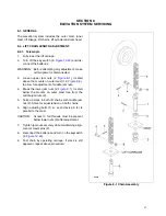
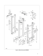
Figure 8-1

), located

above the mounts of cylinder (44, 

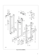
Figure 8-3

), to

allow for adjustment of middle jam nuts.

4.

Break the lower jam nuts (2, 

Figure 8-1

), located

below the mounts of the cylinder, free from the
middle jam nuts (2).

5.

Take up slack in both lift chains with middle jam
nut (2, 

Figure 8-1

). Strive for equal tension on

both chains.

6.

Align anchors (1) so each clevis pin (4) is parallel
to the mast.

CAUTION:

At least 3 full threads must be present
below lower nut (2, 

Figure 8-1

) after

adjustment.

7.

Tighten jam nuts securely while maintaining align-
ment of clevis pins (4).

8.

Reconnect the batteries and turn on the keyswitch
(6, 

Figure 12-22

).

9.

Test chain by operating carriage. If slack is still
apparent, repeat above procedure.

8-2.3. TRIMAST Secondary Lift Chain

1.

Fully lower the lift carriage.

2.

Turn off the key switch (6

Figure 12-22

) and dis-

connect the batteries.

WARNING: Before attempting any adjustment, make

certain power is disconnected.

3.

Loosen jam nuts (2, 

Figure 8-1

), the mount of

outer mast (25, 

Figure 8-3

), to allow for adjust-

ment of middle jam nut.

4.

Break the lower jam nuts (2, 

Figure 8-1

), located

below the mount of outer mast free from the mid-
dle jam nuts.

5.

Take up slack in both lift chains with middle jam
nut (2). Strive for equal tension on both chains.

6.

Align anchors (1) so each clevis pin (4) is parallel
to the outer mast (25, 

Figure 8-3

).

CAUTION:

At least 3 full threads must be present
below lower nut (2, 

Figure 8-1

) after

adjustment.

7.

Tighten jam nuts securely while maintaining align-
ment of clevis pins (4).

8.

Reconnect the batteries and turn on the keyswitch
(6, 

Figure 12-22

).

9.

Test chain by operating carriage. If slack is still
apparent, repeat above procedure.

8-3. LIFT CHAIN WEAR INSPECTION.

Both lift chains should be replaced when either chain
is worn enough to increase it’s length by 3% or more.
To make this determination proceed as follows.
Using a section of chain that sees the most frequent
operation over the chain sheaves, isolate a vertical
portion under tension from the weight of carriage and
forks.
Measure the distance between pin centers on 20 verti-
cal links. If the section measures 12.88” or more, the
chain should be replaced.
New chain anchor pins should be installed when
chains are replaced. Never replace a partial section of
chain and never repair chain. Refer to paragraph 

8-4.

when installing new chain.

49

Содержание BGL-22

Страница 1: ...STACKER ISSUE DATE MAY 5 2020 REV 0 PART 038 926E WARNING Do not operate or service this product unless you have read and fully understand the entire contents of this manual Failure to do so may resu...

Страница 2: ...care when operating on ramps travel slowly and do not angle or turn Travel with load downhill Do not overload truck Check nameplate for capacity and load center information When using forks space for...

Страница 3: ...1 9 TILT SWITCH REPLACEMENT 5 6 5 2 STEERING ARM 5 6 5 2 1 RETURN SPRING REPLACEMENT 5 6 5 2 2 STEERING ARM REMOVAL 5 6 5 2 3 STEERING ARM INSTALLATION 5 6 5 3 COMPARTMENT COVERS 5 6 5 3 1 REMOVAL 5 6...

Страница 4: ...9 9 7 FREE LIFT CYLINDER TRIMAST 9 10 9 8 SECONDARY LIFT CYLINDER TRIMAST 9 12 9 9 TILT CYLINDER MOUNTING 9 13 9 10 TILT CYLINDER 9 15 10 1 ELECTRICAL SYSTEM 10 2 10 2 ELECTRICAL PANEL 10 3 10 3 TRANS...

Страница 5: ...the truck s main components and controls 1 3 SAFETY FEATURES The BGL 22 is designed and engineered to provide max imum safety for operator and payload Some of the safety features incorporated into th...

Страница 6: ...98 ITEM COMPONENT 1 Chassis 2 Cover 3 Drive wheel 4 Cover 5 Control Handle 6 Battery Indicator 7 Key Switch 8 Front cover 9 Mast 10 Back Rest 11 Forks 12 Load Wheel 13 Hydraulic pump 14 Battery 15 Bat...

Страница 7: ...d person on a regular basis Do not exceed the rated capacity Overloading may result in damage to the hydraulic system and struc tural components Be certain that the lifting machine is operating smootl...

Страница 8: ...d to a safe operating condition Do not make any unauthorized repairs or adjustments All service must be performed by a qualified maintenance technician Table 2 1 Operator Checks ITEM PROCEDURE Transmi...

Страница 9: ...rator Check Off List Date Operator Truck No Model No Dept Check Tires Load Wheels Horn Lift Lower Control Need Maintenance O K Shift Hour Meter Reading Drive Hoist Attachment Operation Forward Reverse...

Страница 10: ...ing the truck 5 Procedures for movement in reverse are the same as in the forward direction except slowly press the speed control backward See Figure 2 3 2 5 1 Stopping The brake pattern of the truck...

Страница 11: ...WER button and hold until forks descend to desired height 2 9 TILT CONTROLS Tilt Control buttons are located on the steering control head Figure 2 4 To tilt forks back push in the TILT BACK button and...

Страница 12: ...NOTES 12...

Страница 13: ...ng soda solution one pound to one gallon of water applied to spilled acid until bub bling stops neutralizes the acid for safe handing and disposal Leakage voltage from battery terminals to battery cas...

Страница 14: ...charging is highly explosive and can cause seri ous injury 1 Charge the battery only in areas designated for that use 2 Make certain the charger being used matches the voltage and amperage of the truc...

Страница 15: ...regulated battery it never requires watering 3 4 CHARGING BATTERIES Charging requirements will vary depending on depth of discharge and temperature Follow safety rules when placing a battery on charge...

Страница 16: ...lift carriage fully lowered spray or brush on a film of SAE 30 or 40 engine oil Table 3 2 Recommended Lubricants See Table 3 3 for Application No 1 Transmission oil EP SAE 80W 90 Transmission oil EP S...

Страница 17: ...2 Full length of channel where rollers operate 2 Lift Chain Brush or Spray No 4 See Paragraph 3 6 3 Lift Carriage Brush No 2 Light coating where forks slide 4 Hydraulic Reservoir Capacity 1 quarts Ca...

Страница 18: ...NOTES 18...

Страница 19: ...wiring A loose con nection may be the cause of malfunction Tighten all loose connections before further troubleshooting b Defective deadman switch 29 Figure 12 1 Check and replace switch if defective...

Страница 20: ...st or carriage roll ers Replace rollers Forks do not lift to top a Oil level too low Add oil to reservoir b Load larger than capacity Refer to I D plate for capacity Weak slow or uneven action of hydr...

Страница 21: ...hange batteries Forks creep downward under load when in a raised position Leak in hydraulic system lift cylin der or lowering valve Check for leaking fitting in hydrau lic line and repair as required...

Страница 22: ...f every alarm occurred This function permits a deeper diagnosis of problems as the recent history can be revisited 4 2 2 2 Logbook Access To view the alarm logbook proceed as follows 1 Connect the Zap...

Страница 23: ...2 Zapi Handset Table 4 2 Set Options R6624 Parameter Factory Setting Description TILLER switch HANDLE This option handles the input CNB 3 Table 4 5 This input opens when the operator leaves the truck...

Страница 24: ...the exclusive hydro becomes active when CNB 7 is opened HOUR COUNTER RUNNING This option specifies the hour counter mode It can be set as RUNNING The counter registers travel time only key on The coun...

Страница 25: ...than the SET POT BRK MIN the minimum release braking strength is applied following the RELEASE BRAKING setting When the pedal potentiometer voltage is equal higher than the SET POT BRK MAX the maximu...

Страница 26: ...specified percentage PERFORMANCE OPTION 1 This option can be set OPTION 1 OPTION 2 QUICK INV LOGIC OPTION 1 This option specifies the active level for the Belly switch input CNB 7 OPTION 1 The quick i...

Страница 27: ...SET POT BRK MIN 0 5 V This setting records the minimum value of braking pedal potentiom eter when the braking pedal switch is closed the procedure is similar to the PROGRAM VACC function This procedur...

Страница 28: ...Maximum truck speed The rela tionship between the accelerator position and the truck speed is linear between the THROTTLE 0 ZONE and the X point and also between the X point and the maximum accelerato...

Страница 29: ...ccelerate RELEASE BRAKING LEVEL 5 Level 0 to 9 It controls the deceleration ramp when the travel request is released At Level 9 the truck brakes abruptly INVERS BRAKING LEVEL 4 Level 0 to 9 It control...

Страница 30: ...the forward or reverse switch is closed but the accelerator at its minimum In the ACO sense Coils this setting is higher equal than 5 Hz RPM CREEP 100 A Percentage value Set to 100 and not Used MAXIM...

Страница 31: ...tt Maximum current 3 A CNA 4 NPC Negative of pump contactor soil CNA 5 PPC PEV Positive of pump contactor coil and lowering electrovalve coil CNA 6 NEV Negative of the lowering electrovalve coil CNA 7...

Страница 32: ...cover CNB 2 CM Common for FW BW SR1 SR2 TILLER H S BELLY LIFTING LOWERING microswitches This connection supplies a keyswitch voltage level CNB 3 TILLER SW Tiller request input Must be connected to the...

Страница 33: ...RXD Negative serial reception CNC 3 PCLTXD Positive serial transmission CNC 4 NCLTXD Negative serial transmission CNC 5 GND Negative console power supply CNC 6 12V Positive console power supply CNC 7...

Страница 34: ...NOTES 34...

Страница 35: ...CONTROL HEAD 5 1 1 Cap Assembly Removal 1 Turn off the key switch 6 Figure 12 22 and dis connect the batteries 2 Remove four screws 17 Figure 5 1 lift up cap assembly 21 and disconnect harness 23 from...

Страница 36: ...Figure 5 1 in place and connect harness 23 to harness 28 Figure 5 2 2 Position cap assembly 21 Figure 5 1 on control head and secure with four screws 17 3 Reconnect the batteries and turn on the key...

Страница 37: ...racket 20 and secure with screw 16 lock washer 6 and flat washer 7 8 Install screw 1 lock washer 6 and flat washer 7 9 Install control knob 14 on potentiometer 15 and secure with screw 4 and washer 3...

Страница 38: ...ssembly as described in para graph 5 1 2 5 1 8 Lift and Lower Switch Replacement 1 Remove the cap assembly as described in para graph 5 1 1 2 Remove switch assembly 1 Figure 5 4 form cap 17 3 Remove p...

Страница 39: ...Figure 5 4 Cap Assembly R6878 39...

Страница 40: ...s seat inside steering arm 2 6 Position the new gas return spring 3 inside the steering arm being sure it fully engages its seat 7 Position the opposite end of the gas return spring 3 on bracket 17 an...

Страница 41: ...aragraph 5 3 4 Remove the steering arm as described in para graph 5 2 2 5 Disconnect electric brake 1 Figure 6 1 from the harness 1 Figure 12 25 6 Remove three screws 2 Figure 6 1 and remove brake 1 7...

Страница 42: ...Figure 6 1 Transmission Motor Brake Assembly R6879 42...

Страница 43: ...and remove the six screws 7 six lock washers 8 and six flat washers 9 8 Slowly lower the transmission out the bottom of the frame 9 Install new transmission by reversing the steps above 7 3 Load Wheel...

Страница 44: ...Figure 7 1 Transmission Motor Brake Assembly R6879 44...

Страница 45: ...Figure 7 2 Load Wheels R6882 45...

Страница 46: ...NOTES 46...

Страница 47: ...8 2 to allow for adjustment of middle jam nuts 4 Break the lower jam nuts 2 Figure 8 1 located below the mounts on outer mast free from the middle jam nuts 2 5 Take up slack in both lift chains with m...

Страница 48: ...Figure 8 2 Elevation System Telescopic R6883 48...

Страница 49: ...nuts 2 Figure 8 1 the mount of outer mast 25 Figure 8 3 to allow for adjust ment of middle jam nut 4 Break the lower jam nuts 2 Figure 8 1 located below the mount of outer mast free from the mid dle...

Страница 50: ...Figure 8 3 Mast TRIMAST R6884 50...

Страница 51: ...n 4 connecting chain 5 to chain anchor 6 at the lift carriage 5 Remove cotter pin 3 and clevis pin 4 connect ing chain 5 to chain anchor 1 at free lift cylinder 44 Figure 8 3 6 Remove chain from sheav...

Страница 52: ...NOTES 52...

Страница 53: ...er level Use hydraulic oil listed in Table 3 2 9 Install the front compartment covers as described in paragraph 5 3 9 2 HYDRAULIC PUMP AND MOTOR ASSY WARNING When forks are raised pressure exists in t...

Страница 54: ...Figure 9 1 Hydraulic System R6886 54...

Страница 55: ...and disconnect hose 18 Figure 9 3 to pump and motor 5 4 Connect electrical leads to pump and motor 5 5 Fill the hydraulic reservoir Use hydraulic oil listed in Table 3 2 6 Reconnect the batteries and...

Страница 56: ...Figure 9 3 Hydraulic System TRIMAST R6888 56...

Страница 57: ...base of the cylinder 2 Remove gland nut 7 Figure 9 5 3 Remove wiper ring 8 and O ring 9 from gland nut 7 4 Pull out piston rod 1 5 Remove bushing 4 and bearing 5 6 Remove piston 2 and O ring 3 from r...

Страница 58: ...Figure 9 4 Elevation System Telescopic R6883 58...

Страница 59: ...Figure 9 5 Lift Cylinder Telescopic R6889 59...

Страница 60: ...ylinder in a vise clamping lightly at the base of the cylinder 2 Remove gland nut 4 Figure 9 7 3 Remove wiper 1 collar 2 packing 3 and O ring 5 from gland nut 4 4 Pull out piston rod 6 5 Remove ring 7...

Страница 61: ...Figure 9 6 Elevation System TRIMAST R6884 61...

Страница 62: ...Figure 9 7 Free Lift Cylinder TRIMAST R6890 62...

Страница 63: ...acking 2 and O rings 4 and 11 from gland nut 3 4 Pull out piston rod 5 5 Remove backup ring 8 retaining ring 7 and bushing 6 from piston rod 5 6 Coat all parts with hydraulic oil Table 3 2 7 Install b...

Страница 64: ...Figure 9 8 Secondary Lift Cylinder TRIMAST R6891 64...

Страница 65: ...ted CAUTION Hydraulic oil can damage parts Wipe off any oil immediately Provide a container under the line or fitting before discon necting 3 Remove the front compartment covers as described in paragr...

Страница 66: ...er body 17 13 Install dust seal 7 O ring 8 snap ring 9 seal 10 O ring 13 and bearing 12 in gland nut 11 14 Install gland nut 11 in tube 17 15 Install retaining rings 3 and bearing 2 in clevis 1 16 Ins...

Страница 67: ...Figure 9 10 Tilt Cylinder R6893 67...

Страница 68: ...NOTES 68...

Страница 69: ...before reconnecting the battery 4 Make sure the connections to the buss bars are tight Use two well insulated wrenches for this task in order to avoid steering the buss bars 10 1 3 Panel Removal 1 Tu...

Страница 70: ...Figure 10 1 Electrical System R6478 R6894 70...

Страница 71: ...Figure 10 2 Electrical Panel R6478 R6895 71...

Страница 72: ...e shaft of motor 17 2 Install drive motor onto transmission Make sure the gears align 3 Reinstall eight screws 4 eight lock washers 5 and eight flat washers 6 to secure the motor to the transmission 4...

Страница 73: ...Figure 10 3 Transmission Motor Brake Assembly R6879 73...

Страница 74: ...NOTES 74...

Страница 75: ...SECTION 11 OPTIONAL EQUIPMENT 75...

Страница 76: ...NOTES 76...

Страница 77: ...SECTION 12 ILLUSTRATED PARTS BREAKDOWN Following is an illustrated parts breakdown of assemblies and parts associated with the BGL 22 Lift Truck 77...

Страница 78: ...Figure 12 1 Steering System R6876 78...

Страница 79: ...3 14 0000 000390 00 WASHER FLAT M5 3 15 0000 000004 00 SCREW M5 X 12 2 16 1120 300004 00 FIXED PLATE 1 17 1120 30000 1 0A BRAKE PLATE 1 18 1120 300006 00 BRACKET 1 19 0000 000088 00 SCREW M4 X 8 2 20...

Страница 80: ...Figure 12 2 Control Head R6877 80...

Страница 81: ...11 0000 000151 00 SCREW M8 X 25 2 12 0000 000159 00 WASHER LOCK M8 2 13 0000 000176 00 WASHER FLAT M8 2 14 1120 340003 00 CONTROL KNOB 1 15 1220 520008 0C POTENTIOMETER 1 16 0000 000004 00 SCREW M5 X...

Страница 82: ...Figure 12 3 Cap Assembly R6878 82...

Страница 83: ...SPRING 8 5 1120 342201 00 BRACKET RIGHT 1 6 1120 342105 00 PIN 6 7 2320 311101 00 BUTTON TILT BACK LEFT 1 8 2320 311102 00 BUTTON TILT FORWARD LEFT 1 9 1120 342101 00 BRACKET LEFT 1 10 1120 342002 00...

Страница 84: ...NO PART NO PART NAME NO REQD 1120 343000 00 EMERGENCY REVERSE SWITCH ASSY 1 1 1120 343002 00 EMERGENCY REVERSE BUTTON 1 2 1120 343003 00 SPRING 2 3 1120 342005 00 PIN 2 4 1120 343001 0A BRACKET 1 5 1...

Страница 85: ...NOTES 85...

Страница 86: ...Figure 12 5 Transmission Motor Brake Assembly R6879 86...

Страница 87: ...R FLAT M8 8 7 0000 000155 00 SCREW M10 X 40 6 8 0000 000063 00 WASHER LOCK M10 6 9 0000 000007 00 WASHER FLAT M10 6 10 1120 230000 00 BEARING 1 11 0000 000013 00 GREASE FITTING M8 1 12 4230 210000 00...

Страница 88: ...NO PART NAME NO REQD 1 0000 000368 00 SCREW M8 X 12 2 2 2214 150002 00 WASHER 2 3 2125 140002 00 UPPER COVER 1 4 0000 000126 00 SCREW M6 X 16 2 5 1120 150002 00 MIDDLE COVER 1 6 2125 140001 00 LOWER C...

Страница 89: ...NOTES 89...

Страница 90: ...Figure 12 7 Frame R6881 90...

Страница 91: ...8 00 SCREW M8 X 10 2 11 2320 100005 00 BAFFLE 2 12 1120 100004 00 BLOCK 2 13 0000 000015 00 SCREW M6 X 10 4 14 2320 110000 00 FRAME 1 15 0000 000373 00 WASHER FLAT M12 8 16 0000 000060 00 WASHER LOCK...

Страница 92: ...Figure 12 8 Load Wheels R6882 92...

Страница 93: ...LOCK M6 4 5 0000 000380 00 WASHER FLAT M6 4 6 2320 601100 00 LOAD WHEEL 2 7 0000 000857 00 BEARING 6309Z 4 8 2320 600001 00 BRACKET 2 9 0000 000233 00 WASHER FLAT M14 4 10 0000 000379 00 WASHER LOCK...

Страница 94: ...Figure 12 9 Elevation System Telescopic R6883 94...

Страница 95: ...4 IN LIFT 2125 610000 00 03 115 IN LIFT 2125 610000 00 04 127 IN LIFT 2125 610000 00 05 135 IN LIFT 2125 610000 00 06 139 IN LIFT 2125 610000 00 07 143 IN LIFT 2125 610000 00 08 151 IN LIFT 2125 61000...

Страница 96: ...Figure 12 10 Elevation System TRIMAST R6884 96...

Страница 97: ...157 IN LIFT 2125 620000 30 02 177 IN LIFT 23 INNER MAST 1 2125 630000 30 01 157 IN LIFT 2125 630000 30 02 177 IN LIFT 24 0000 000244 00 BOLT M10 X 30 1 25 OUTER MAST 1 2125 610000 30 01 157 IN LIFT 21...

Страница 98: ...Figure 12 11 Lift Carriage R6815 98...

Страница 99: ...4 00 SCREW 4 6 2125 612007 00 SNAP RING 4 7 2125 612002 00 ROLLER 4 8 2125 612001 00 ROLLER 4 9 2125 612005 00 DUST SEAL 4 10 0000 000183 00 RETAINING RING 4 11 2125 631000 00 CARRIAGE TELESCOPIC 1 11...

Страница 100: ...5 640000 00 04 127 IN LIFT 107 LINKS 2125 640000 00 05 135 IN LIFT 111 LINKS 2125 640000 00 06 139 IN LIFT 115 LINKS 2125 640000 00 07 143 IN LIFT 117 LINKS 2125 640000 00 08 151 IN LIFT 123 LINKS 212...

Страница 101: ...NOTES 101...

Страница 102: ...Figure 12 13 Hydraulic System R6665 102...

Страница 103: ...10004 00 WASHER 4 5 2320 421000 00 PUMP AND MOTOR FIGURE 12 14 1 6 2320 423000 00 COVER 1 7 0000 000056 00 WASHER LOCK M6 4 8 0000 000620 00 BOLT M6 X 16 4 9 2320 422000 00 HYDRAULIC RESERVOIR 1 10 21...

Страница 104: ...Figure 12 14 Pump Motor R6886 104...

Страница 105: ...REW M6 X 12 4 9 2320 421008 00 RELAY 1 10 2320 421009 00 BUS BAR 1 11 2320 421010 00 WIRE 1 12 2320 421011 00 CLAMP 1 13 2320 421012 00 TUBE PLASTIC 3 14 2320 421013 00 FILTER STEEL 1 15 2320 421014 0...

Страница 106: ...scopic R6887 INDEX NO PART NO PART NAME NO REQD 1 2320 410000 00 HOSE ASSEMBLY 1 2 0000 000044 00 SEAL 2 3 2401 163500 00 BOLT M16 X 35 1 4 0000 000069 00 SEAL 2 5 2402 143500 00 BOLT G1 4 X 35 1 INDE...

Страница 107: ...NOTES 107...

Страница 108: ...Figure 12 16 Hydraulic System TRIMAST R6888 108...

Страница 109: ...00044 00 SEAL 2 9 2125 430000 3A B TUBE ASSEMBLY 1 10 0000 000069 00 SEAL 2 11 2805 160014 00 BOLT M16 X 1 5 1 12 HOSE 1 2125 440000 3A 01 157 IN LIFT 2125 440000 3A 03 177 IN LIFT 13 2125 450000 30 B...

Страница 110: ...Figure 12 17 Tilt Cylinder Mounting R6892 110...

Страница 111: ...O PART NAME NO REQD 1 05782 08200A BOLT M8 X 20 2 2 0000 000159 00 WASHER LOCK M8 2 3 0000 000176 00 WASHER FLAT M8 2 4 3218 840000 00 SHAFT 2 5 CYLINDER TILT FIGURE 12 21 REF INDEX NO PART NO PART NA...

Страница 112: ...Figure 12 18 Lift Cylinder Telescopic R6889 112...

Страница 113: ...YLINDER 139 IN LIFT 1 2110 410000 00 09 LIFT CYLINDER 143 IN LIFT 1 2110 410000 00 10 LIFT CYLINDER 151 IN LIFT 1 2110 410000 00 11 LIFT CYLINDER 161 IN LIFT 1 1 PISTON ROD 1 2 2125 410002 00 PISTON 1...

Страница 114: ...Figure 12 19 Free Lift Cylinder TRIMAST R6890 114...

Страница 115: ...5 420000 30 02 LIFT CYLINDER 177 IN LIFT 1 1 0000 000045 00 WIPER RING 1 2 0000 000684 00 COLLAR 1 3 0000 000046 00 PACKING 1 4 2125 420002 30 GLAND NUT 1 5 0000 000685 00 O RING 1 6 PISTON ROD 1 7 21...

Страница 116: ...Figure 12 20 Secondary Lift Cylinder TRIMAST R6891 116...

Страница 117: ...1 0000 000084 00 WIPER RING 1 2 0000 000085 00 PACKING 1 3 2125 410004 30 GLAND NUT 1 4 0000 000519 00 O RING 1 5 PISTON ROD 1 6 2125 410005 30 BUSHING 1 7 0000 000520 00 RETAINING RING 1 8 2125 41000...

Страница 118: ...Figure 12 21 Tilt Cylinder R6893 118...

Страница 119: ...OCK 1 6 0000 000229 00 NUT M14 X 1 5 1 7 3218 810002 00 DUST SEAL 1 8 3218 810006 00 O RING 1 9 58605 15T11 SNAP RING 1 10 3218 810005 00 SEAL 1 11 58602 15T11 GLAND NUT 1 12 3218 810001 00 BEARING 1...

Страница 120: ...Figure 12 22 Electrical System R6894 120...

Страница 121: ...2 23 REF 6 1220 520002 0C KEY SWITCH 1 7 1120 500016 00 KEY 1 8 0000 000170 00 SCREW M6 X 30 2 9 0000 000056 00 WASHER LOCK M6 2 10 2320 531000 00 CONNECTOR BATTERY 1 11 1120 112008 00 SPACER 1 12 122...

Страница 122: ...500004 00 CONTROLLER 1 6 1120 530007 00 BUSS BAR 1 7 0000 000123 00 WASHER FLAT M6 7 8 0000 000056 00 WASHER LOCK M6 7 9 0000 000166 00 NUT M6 5 10 1120 500005 00 CONTACTOR 1 11 0000 000077 00 SCREW...

Страница 123: ...NOTES 123...

Страница 124: ...Figure 12 24 Drive Motor R6630 124...

Страница 125: ...ERMINAL BLOCK 1 4 0000 000206 00 WASHER LOCK M5 17 5 0000 000117 00 SCREW M5 X 10 2 6 0000 000166 00 NUT M6 6 7 0000 000056 00 WASHER LOCK M6 6 8 1120 220002 00 BEARING 1 9 0000 000204 00 KEY 3 x 5 x...

Страница 126: ...Figure 12 25 Wiring Harness R6896 INDEX NO PART NO PART NAME NO REQD 1 2320 520001 00 WIRE HARNESS 1 2 1120 500010 00 FUSE 10A 1 INDEX NO PART NO PART NAME NO REQD 126...

Страница 127: ...NO PART NO PART NAME NO REQD 1 2320 530007 00 PUMP POWER CABLE 1 2 2320 530006 00 PUMP POWER CABLE 1 3 2320 530004 00 MOTOR CABLE V 1 4 2320 530003 00 MOTOR CABLE U 1 5 2320 530005 00 MOTOR CABLE W 1...

Страница 128: ...NOTES 128...

Страница 129: ...129...

Страница 130: ...sauga ON Canada L5T 2N6 t 905 457 3900 f 905 457 2313 USA 6350 Burnt Poplar Road Greensboro NC 27409 www bluegiant com If calling within North America t 1 800 668 7078 f 1 888 378 5781 Copyright Blue...

Отзывы: