background image

Freshbox 100 WiFi

8

www.blaubergventilatoren.de

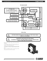
2 holes (Ø 120 mm) for an air duct Ø 130 mm

Fill the gaps between the wall and 

the air ducts with a mounting foam

4 holes (Ø 8 and 90 mm deep) 

in the wall made using 

a mounting template

Power cable entry

Power cable entry

2 holes (Ø 120 mm) for an air duct Ø 100 mm

Fill the gaps between the wall and 

the air ducts with a mounting foam

4 holes in the wall

Ø 8 and 90 mm deep

416.5

647

205

162

468.5

102.5

76

400

73.5

547

91

230

170

188.5

158.5

77

ADDITIONAL HOLE!

DRILL UPON CUSTOMER’S REQUEST ONLY!

Ø 120 mm hole for Ø 100 mm air duct

Fill the gaps between the wall and the air ducts 

with a mounting foam

ADDITIONAL HOLE!

DRILL UPON CUSTOMER’S REQUEST ONLY!

Ø 120 mm hole for Ø 100 mm air duct

Fill the gaps between the wall and the air ducts 

with a mounting foam

Hole spacing template

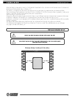
THE UNIT MUST BE MOUNTED ON A PLANE SURFACE.

MOUNTING OF THE UNIT TO AN UNEVEN SURFACE CAN LEAD TO THE UNIT CASING 

DISTORTION AND OPERATION DISTURBANCE.

BEFORE MOUNTING MAKE SURE THE CASING DOES NOT CONTAIN ANY FOREIGN 

OBJECTS (E.G. FOIL, PAPER).

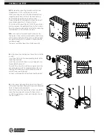
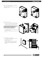
1. 

Mark and drill holes in the wall using a mounting 

template.
Fix the mounting template at the required level on 
the wall with a self-adhesive tape.
Using a mounting template make marks to drill holes 
for air ducts, for unit mounting and for power cable 
entry.
Before installation operations route necessary cables 
and wires to the unit mounting place.

Unit mounting

Содержание Freshbox 100 ERV

Страница 1: ...Heat recovery air handling unit USER S MANUAL EN Freshbox 100 WiFi ...

Страница 2: ...and operating principle 6 Installation and set up 7 Connection to power mains 11 Control 12 Technical maintenance 22 Troubleshooting 23 Storage and transportation regulations 23 Manufacturer s warranty 24 Certificate of acceptance 25 Seller information 25 Installation certificate 25 Warranty card 25 This user s manual is a main operating document intended for technical maintenance and operating st...

Страница 3: ...rotect the electric parts of the unit against ingress of water Do not allow children to operate the unit Disconnect the unit from power mains prior to any technical maintenance Do not store any explosive or highly flammable substances in close proximity to the unit When the unit generates unusual sounds odour or emits smoke disconnect it from power supply and contact the Seller Do not open the uni...

Страница 4: ...rials coarse dust soot and oil particles or environments favourable for the formation of hazardous substances toxic substances dust pathogenic germs THE UNIT SHOULD NOT BE OPERATED BY CHILDREN OR PERSONS WITH REDUCED PHYSICAL MENTAL OR SENSORY CAPACITIES OR THOSE WITHOUT THE APPROPRIATE TRAINING THE UNIT MUST BE INSTALLED AND CONNECTED ONLY BY PROPERLY QUALIFIED PERSONNEL AFTER THE APPROPRIATE BRI...

Страница 5: ...ation foam rubber 10 mm Heat recovery efficiency 96 94 92 89 87 96 94 92 89 87 96 94 92 89 87 96 94 92 89 87 Heat exchanger type counter flow Heat exchanger material polystyrene Supply filter G4 F8 option F8 Carbon H13 G4 F8 option F8 Carbon H13 G4 G4 Extract filter G4 Connected air duct diameter mm Ø 100 Weight kg 31 31 31 31 Parameter Freshbox 100 ERV WiFi Freshbox E 100 ERV WiFi Freshbox E1 100...

Страница 6: ...ply air preheater or reheater with overheating protection The Freshbox E 100 WiFi Freshbox E2 100 WiFi units are equipped with a preheater The preheater is located upstream of the heat exchanger and is designed for its overheating protection The Freshbox E1 100 WiFi Freshbox E2 100 WiFi units are equipped with a reheater Thereheaterislocateddownstreamoftheheatexchangerandisdesignedforextraheatingo...

Страница 7: ...en supply and extract air flows in units with polystyrene heat exchangers lead to condensate formation Condensate is collected in the drain pan and is removed outside by the drain pipes through the exhaust air duct Condensate is not formed in units equipped with an enthalpy heat exchanger as moisture is transferred from one air flow to another through a membrane The louvre shutters open automatica...

Страница 8: ...he air ducts with a mounting foam ADDITIONAL HOLE DRILL UPON CUSTOMER S REQUEST ONLY Ø 120 mm hole for Ø 100 mm air duct Fill the gaps between the wall and the air ducts with a mounting foam Hole spacing template THE UNIT MUST BE MOUNTED ON A PLANE SURFACE MOUNTING OF THE UNIT TO AN UNEVEN SURFACE CAN LEAD TO THE UNIT CASING DISTORTION AND OPERATION DISTURBANCE BEFORE MOUNTING MAKE SURE THE CASING...

Страница 9: ...he outer ventilation hood For details refer to the installation instruction for the ventilation hood The outer ventilation hood is available separately 3 Fix the mounting template on the wall to install the air ducts Insert the air ducts in the corresponding holes of the mounting template Install the air duct with the minimum slope of 3 mm for condensate removal To install the unit with an additio...

Страница 10: ...wall mounted air ducts CAUTION REMOVE THE MAGNETIC PLUG FROM THE EXHAUST GRILLE IF AN ADDITIONAL EXTRACT SPIGOT IS NOT INSTALLED Fix the unit on the wall using the supplied screws and expansion anchors Install the heat exchanger back and close the unit door 7 Install the outer ventilation hood Cut a part of the drain pipe protruding outside to a length not more than 10 mm Remove the foam excess Fi...

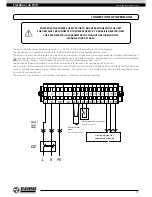
Страница 11: ...uipped with an automatic circuit breaker QF built into the stationary wiring to open the circuit in the event of overload or short circuit The position of the external automatic circuit breaker must ensure free access for quick power off of the unit The trip current of the automatic circuit breaker must exceed the maximum current consumption of the unit refer to the Technical data section The reco...

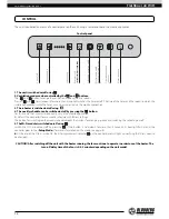
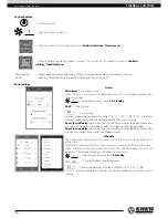
Страница 12: ...reheater is switched on off using 4 The weekly schedule can be switched on off by pressing the button For this mode the time must be correctly set via the mobile application By default the controller stores a weekly schedule with factory settings The button for switching on the weekly schedule blocks the buttons for changing speeds and switching the reheating on off 5 TheWi Fi module is switched o...

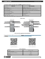
Страница 13: ...nds to switching of the fifth speed Corresponds to switching of the third speed Activation of the first speed Unit on off Increase of the reheater temperature setpoint Decrease of the reheater temperature setpoint Reheater on off Week scheduled operation on off Timer on off Unit On Off Week scheduled operation on off Timer On Off Freshbox E 100 WiFi Freshbox E1 E2 100 WiFi Corresponds to switching...

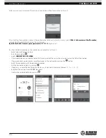
Страница 14: ...ication on the mobile device connected to the unit Select a desired connection type Enter the app menu Select CONNECTION AT HOME If the mobile device is connected to the Wi Fi access point of the unit without a router select the Default connection If you are connecting via a router search for devices in the network by pressing the button Select the connection with the required ID number Edit the c...

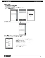
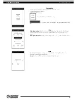
Страница 15: ...hen press Receive The screen will display the current Wi Fi parameter settings Select one of the Wi Fi operation modes Access Point or Client Access Point access point mode without a home router Up to 8 devices can be connected to the unit in this mode Select the desired security level for the Access point mode Open without a password WPA PSK password protected WPA2 PSK password protected WPA WPA2...

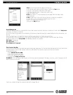
Страница 16: ...seconds before the LED on the button starts flashing The unit will continue in this mode for 3 minutes and then automatically revert to the previous settings To immediately exit the Setup mode press and hold the button again for 5 seconds until the LED on the button stops flashing To connect to the unit in the Setup Mode the following parameters are available Wi Fi name Setup mode Wi Fi password 1...

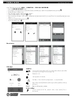
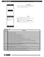
Страница 17: ...ed on the control board and the casing of the unit and also the device password default 1111 Confirm the updated details by pressing To exit the account press Menu structure Home page Indicators Current type of connection to the unit Home connection or connection via a cloud server through Internet respectively Reheater activity Filter replacement indicator Red colour alarm indication orange colou...

Страница 18: ...n Available 15 С 30 С off If OFF is selected temperature control will not be performed while the timer is running Boost turn off delay determines the turn off delay time for the Boost mode after the signal at the digital input Boost switch disappears on the control board Boost turn on delay determines the turn on delay time for the Boost mode after the signal is applied to the digital input Boost ...

Страница 19: ...ll be automatically set Filter Filter timer setup When the set time 70 365 days has elapsed the filter change indicator appears and filter replacement information is displayed in the Alarms menu Total operation time Displays the running time of the unit which cannot be reset Other The backlight brightness changes dynamically after releasing the button the brightness decreases to a preset level Sou...

Страница 20: ... current status of all sensors outdoor air temperature supply air temperature extract air temperature upstream of the heat exchanger exhaust air temperature downstream of the heat exchanger Boost mode sensor Fire alarm sensor Preheater thermostat sensor Reheater thermostat sensor Firmware This section displays the current version and date of the controller and control board firmware ...

Страница 21: ...thermostat 11 Alarm Actuation of the main heater thermostat 23 Warning The battery is low The scheduler function will be incorrect 25 Alarm Fire alarm activation 40 Warning The filter replacement timer has expired The filter must be replaced 50 Alarm No connection between the control panel and the controller 51 Alarm No additional supply air temperature sensor detected before main heater Alarm War...

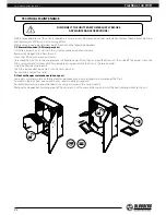
Страница 22: ...ner To remove the G4 filters for cleaning remove the flexible clamps fixing them and pull the filters until they slide off the guides Clean the filters with water and let them dry After complete drying reassemble the filters in the reverse order Install the filters back to the unit The filters require cleaning not less than 3 4 times per year For new filters contact the Seller 2 Heat exchanger mai...

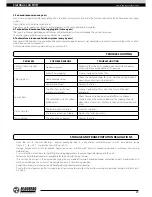
Страница 23: ...icing Check the heat exchanger for icing Stop the unit operation if necessary and wait until the ice melts Heater malfunction Contact the Seller Low air flow The filters fans or the heat exchanger are soiled Clean or replace the filters clean the fans and the heat exchanger The ventilation system is soiled or damaged Check for unobstructed opening of diffusers and louver shutters check the exhaust...

Страница 24: ...rranty does not apply to the following cases User s failure to submit the unit with the entire delivery package as stated in the user s manual including submission with missing component parts previously dismounted by the user Mismatch of the unit model and the brand name with the information stated on the unit packaging and in the user s manual User s failure to ensure timely technical maintenanc...

Страница 25: ...very with the user s manual The warranty terms are acknowledged and accepted Customer s Signature The Freshbox_____100_____WiFi unit has been connected to power mains pursuant to the requirements stated in the present user s manual Installation Stamp Seller Address Phone Number Installation Technician s Full Name Installation Date Signature The unit has been installed in accordance with the provis...

Страница 26: ...Freshbox 100 WiFi 26 www blaubergventilatoren de ...

Страница 27: ...www blaubergventilatoren de Freshbox 100 WiFi 27 ...

Страница 28: ...www blaubergventilatoren de B73 9EN 03 ...

Отзывы: