background image

www.blaubergventilatoren.de

vento eco

12

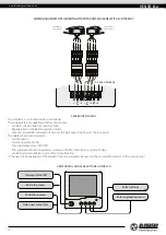
WIRING DIAGRAM FOR THE VENTILATOR WITH CONTROL PANEL WITH LCD DISPLAY 

100-230 V 50/60 Hz

P2

+

-

+

P1

-

L

N

P1

+

-

+

P2

-

BLA

CK

RED

BL

UE

YELL

OW 

Ventilator 2

(Air extract)

BLA

CK

RED

BL

UE

YELL

OW 

Ventilator 1

(Air supply)

VENTILATOR CONTROL

The ventilator is controlled via the control panel. 
These parameters are editable with the control panel: 
•  ventilator speed stage: low, medium, high 
•  Regeneration or Ventilation operation mode 
•  timer-based ventilator operation: 4 hours at the high speed or 8 hours at the low speed.
The display shows the parameters: 
•  current speed 
•  current operation mode 
•  timer operating status (ON/OFF)
•  filter replacement/servicing need according to the filter timer (factory setting 90 days)
•  ventilator alarm shutdown in case of motor malfunction 
In the event of de energizing of the ventilator the set parameters are saved in the non-volatile memory of the control panel.

UNIT CONTROL USING THE BUTTONS ON THE LCD 

Turning unit on/off 

Enter engineering menu

Select settings 

Open next menu item

Exit setup menu

Enter setup menu

Содержание VENTO Eco A50-4 Pro1

Страница 1: ...Heat regeneration single room reversible ventilator USER S MANUAL EN VENTO Eco A50 4 Pro1 VENTO Eco2 A50 4 Pro1...

Страница 2: ...construction electrical and technical norms and standards must be observed when installing and operating the unit Disconnect the unit from the power supply prior to any connection servicing maintenan...

Страница 3: ...owledge unless they have been given supervision or instruction concerning use of the appliance by a person responsible for their safety Children should be supervised to ensure that they do not play wi...

Страница 4: ...rille type 4 white internal grille with a smooth panel Rated air capacity m3 h Air duct cross section A round Ventilator series VENTO Eco series with one ventilator and one control panel VENTO Eco2 se...

Страница 5: ...IP24 The unit design is constantly being improved thus some models may be slightly different from those described in this manual A 160 Air duct length wall thickness Outer ventilation hood Indoor unit...

Страница 6: ...l to prevent ingress of water and foreign objects into the ventilator Front part of the indoor unit Fulfils the decorative function It is a part of the indoor unit design and directs the air flow upwa...

Страница 7: ...from the room As it flows through the regenerator it heats and moisturizes the regenerator transferring heat and air moisture 70 seconds after the ceramic regenerator starts to get warmed the ventila...

Страница 8: ...ide Do not disconnect the connectors on the circuit boards in the casing 3 Connect the wires to the terminal blocks on the back side of the control panel in compliance with external wiring diagrams Fi...

Страница 9: ...ecommended to make preparations for layout of the power cable and other required cables in the wall The hole size and minimum distance to the surface e g wall ceiling or window and the minimum distanc...

Страница 10: ...rk the point 1 on the sound absorbing mat on the level of the air duct edge Cut out the excessive part of the sound absorbing mat Insert the adjusted sound absorbing roll in the air duct Do not use an...

Страница 11: ...the following criteria Always use shielded cables Wire cross section depends on the length and is selected according to the table below Cable length m Minimum wire cross section in the cable mm2 5 0 2...

Страница 12: ...n operation mode timer based ventilator operation 4 hours at the high speed or 8 hours at the low speed The display shows the parameters current speed current operation mode timer operating status ON...

Страница 13: ...w speed middle speed high speed timer Parameter setting using the or buttons 4 hours at the high speed 8 hours at the low speed turning timer off The ventilator reverts to operation with a previous sp...

Страница 14: ...ventilator will run at the permanent low speed speed setting Parameter setting using the or buttons Set the value 5 6 Return to user menu Press several times the button till the main window of the us...

Страница 15: ...Ventilation mode The ventilator runs exclusively in the supply or extract mode In case of installation of two ventilators the air flow direction depends on the external wiring refer the wiring diagra...

Страница 16: ...wn 90 days the control panel displays the filter replacement indicator Wash the filters and let those dry out completely Install the dry filters in the air duct Vacuum cleaning is allowed To reset the...

Страница 17: ...ing temperature for at least 3 4 hours TROUBLES ANDTROUBLESHOOTING Trouble Possible reasons Troubleshooting The fan does not move up during start up of the unit The control panel displays no informati...

Страница 18: ...ismantling unit setup To benefit from warranty repair the user must provide the unit the user s manual with the purchase date stamp and the payment paperwork certifying the purchase The unit model mus...

Страница 19: ...ION CERTIFICATE The VENTO Eco ____________ unit is installed pursuant to the requirements stated in the present user s manual Installation Stamp Company name Address Phone Number Installation Technici...

Страница 20: ...www blaubergventilatoren de B127 1EN 01...

Отзывы: