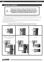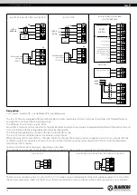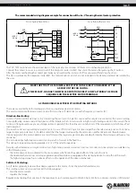
The recommended wiring diagram example for connection of the Iso-V fan using thermal motor protection
For a single-phase motor
For a three-phase motor
L
N
X1
1
2
3
N
L
QF
PE
~230 V
Hz
50
4
1
2
5
6
3
4
1
2
5
6
7
3
4
РЕ
L
N
X1
N
L
QF
PE
~230 V
Hz
50
TW1
TW2
TW1
TW2
TW1
TW2
TW1
TW2
TW1
TW2
TW1
TW2
W2
W1
V2
TW1
TW2
РЕ
L
N
X1
N
L
QF
PE
~230 V
Hz
50
РЕ
Х
2
NC
COM
Х
1
1
2
3
4
PE
L1
L2
L3
5
1
2
3
4
5
6
NC
COM
QF
L1
L2
L3
PE
~380 V
Hz
50
L2
L1
QF
PE
~400V
Hz
50
L2
L1
X1
2
7
1
3
L3
L3
5
4
6
V1
U1
PE
U2
TW1
TW2
W2
W1
V2
V1
U1
PE
U2
L1
L2
L3
8
9
РЕ
L2
L1
QF
PE
~400 V
Hz
50
L2
L1
X1
2
7
1
3
2
1
3
2
1
3
L3
L3
5
4
6
L1
L2
L3
8
9
TW2
TW1
TW1
TW2
PE
L
QF
~230 V
Hz
50
N
L
X1
PE
N
PE
+10V
0-10V
GND
+10V
CTR
GND
+10V
CTR
GND
+10V
CTR
GND
X2
QF PE
N
L
Х
1
~230 V
Hz
50/60
1
2
3
4
5
PE
N
L
Х
2
1
2
3
4
5
0-10V
RSB
RSA
GND
+10V
0-10V
RSB
RSA
GND
+10V
KL1
PE
L3
~400 V
50 Hz
QF
KL3
+20 V
0-10 V
RSA
RSB
RSA
RSB
GND
4-20 mA
+10 V
0-10 V
GND
OUT
KL2
NO
COM
NC
L1
L2
L2
L1
L3
PE
Подключение
аналогового
выхода
0-10 V
прибора
управления
0-10 V
GND
KL3
Подключение
релейного
выхода
прибора
управления
0-10 V
+10 V
KL3
KL3
Подключение
регулятора
(
потенциометра
)
0-10 V GND
+10 V
Подключение
датчика
критического
давления
4-20 mA
4-20 mA +20 V
KL3
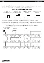
Схема
внешних
подключений
и
универсального
соединения
вентиляторов
с
ЕС
-
двигателями
в
группу
L
N
X1
X1
1
2
3
L
QF
N
PE
TW1
4
5
6
TW2
~230 V
Hz
50
KM1
S1
“ON”
S2
“OFF”
KM1
РЕ
L1
TW1
TW2
S1
“ON”
S2
“OFF”
KM1
L2
L3
QF
~400 V
Hz
50
L1
L2
L3
N
PE
PE
L
N
X1
1
2
3
N
L
QF
PE
~230 V
Hz
50
4
1
2
5
6
3
4
1
2
5
6
7
3
4
РЕ
L
N
X1
N
L
QF
PE
~230 V
Hz
50
TW1
TW2
TW1
TW2
TW1
TW2
TW1
TW2
TW1
TW2
TW1
TW2
W2
W1
V2
TW1
TW2
РЕ
L
N
X1
N
L
QF
PE
~230 V
Hz
50
РЕ
Х
2
NC
COM
Х
1
1
2
3
4
PE
L1
L2
L3
5
1
2
3
4
5
6
NC
COM
QF
L1
L2
L3
PE
~380 V
Hz
50
L2
L1
QF
PE
~400V
Hz
50
L2
L1
X1
2
7
1
3
L3
L3
5
4
6
V1
U1
PE
U2
TW1
TW2
W2
W1
V2
V1
U1
PE
U2
L1
L2
L3
8
9
РЕ
L2
L1
QF
PE
~400 V
Hz
50
L2
L1
X1
2
7
1
3
2
1
3
2
1
3
L3
L3
5
4
6
L1
L2
L3
8
9
TW2
TW1
TW1
TW2
PE
L
QF
~230 V
Hz
50
N
L
X1
PE
N
PE
+10V
0-10V
GND
+10V
CTR
GND
+10V
CTR
GND
+10V
CTR
GND
X2
QF PE
N
L
Х
1
~230 V
Hz
50/60
1
2
3
4
5
PE
N
L
Х
2
1
2
3
4
5
0-10V
RSB
RSA
GND
+10V
0-10V
RSB
RSA
GND
+10V
KL1
PE
L3
~400 V
50 Hz
QF
KL3
+20 V
0-10 V
RSA
RSB
RSA
RSB
GND
4-20 mA
+10 V
0-10 V
GND
OUT
KL2
NO
COM
NC
L1
L2
L2
L1
L3
PE
Подключение
аналогового
выхода
0-10 V
прибора
управления
0-10 V
GND
KL3
Подключение
релейного
выхода
прибора
управления
0-10 V
+10 V
KL3
KL3
Подключение
регулятора
(
потенциометра
)
0-10 V GND
+10 V
Подключение
датчика
критического
давления
4-20 mA
4-20 mA +20 V
KL3
Схема
внешних
подключений
и
универсального
соединения
вентиляторов
с
ЕС
-
двигателями
в
группу
L
N
X1
X1
1
2
3
L
QF
N
PE
TW1
4
5
6
TW2
~230 V
Hz
50
KM1
S1
“ON”
S2
“OFF”
KM1
РЕ
L1
TW1
TW2
S1
“ON”
S2
“OFF”
KM1
L2
L3
QF
~400 V
Hz
50
L1
L2
L3
N
PE
PE
The TW1, TW2 terminals are the electrical leads of the normally closed contact of the motor overheating protection.
Connect the contact in series to power circuit of the magnetic starter coil KM1 that starts the motor after pressing the S1 button.
After the motor overheating the contact gets broken and switches the starter coil off to cut power off and stop the motor.
The QF circuit breaker, the magnetic starter KM1, the control knobs S1 and S2 are not included in the delivery and must be installed by
the user.
ASYNCHRONOUS ELECTRIC MOTOR STARTING METHODS
There are several methods for starting asynchronous squirrel-cage electric motors.
The most common methods are: direct-on-line (DOL), with a soft starter (SS) or with a frequency converter (FC).
Direct-on-line starting
In case of direct-on-line starting (i.e. by connecting the motor to the electric mains with a simple line contactor), the motor starting
time significantly increases due to high inertia of the impeller, which, in turn, results in high in-rush starting currents in the circuit. These
currents of long duration may cause voltage slumps (especially if the feed line section falls short of the requirements), which may affect
load operation.
The in-rush current consumed by an electric motor in case of DOL starting is 5-8 times larger than the rated value (or even 10-14 times
larger in some rare instances). It should be noted that the torque developed by the motor also significantly exceeds the rated value.
Upon energisation the motor operates as a transformer with a squirrel-cage secondary winding formed by the rotor cage with a very low
resistance.
The rotor develops high induced current causing a rush of current in the feed line.
The startup torque during starting averages 0.5-1.5 of the rated torque value.
Despite such advantages as simple construction, high startup current, quick start and low cost, direct-on-line systems are suitable only
in the following cases:
• the motor power is low compared to the mains power which limits the adverse effect of the rush of current
• the driven mechanism does not require gradual speed build-up or is equipped with a damping device to smooth out the inrush
• the high startup torque has no adverse effects on the operation of the driven mechanism
Soft start. SS starting.
A soft starter gradually increases the voltage supplied to the motor – from the initial to the rated value.
This starting system can be used to meet the following goals:
• limit the motor current
• regulate the torque
Regulation by limiting the current sets the maximum in-rush current equal to 300-400 % (or 250 % in some rare instances) of the rated
MAKE SURE THAT THE FAN IMPELLER ROTATES IN THE DIRECTION MARKED BY THE
ARROW ON THE FAN CASING.
IF NECESSARY, CHANGE THE IMPELLER ROTATION DIRECTION BY ALTERING THE PHASE
SEQUENCE ON THE ELECTRIC MOTOR TERMINALS.
www.blaubergventilatoren.de
iso-V
14


