501-K00 Page 10/12
MAINTENANCE
18. Turn the shaft by hand until a vane slot is at the bottom
(6 o'clock) position of the rotor.
19. Install a new vane (14), ensuring that the rounded edge
is DOWN, and the relief grooves are facing towards the
discharge port. See Figure 7. Repeat this process for all
eight vanes.
20. Install disc (71) on the outboard side of the pump with
the seal cavity facing outward and the disc relief hole
towards the inlet side. Refer to Figure 8.
21. Install seal spacer ring (159) on shaft with outward tangs
of spacer ring engaged with drive holes in rotor.
22. Slide the seal jacket assembly (153C) over the shaft and
into the disc cavity with the drive tangs of the jacket
towards the rotor. Rotate the jacket assembly to engage
the drive tangs in the rotor slots.
23. Apply a small amount of grease to the shaft and the inner
ring of the bearing (24).
24. Install a new rotating O-ring (153E) in the rotating seal
face (153B). With the raised face outward, gently push
the seal face and O-ring over the bearing inner race and
onto the shaft.
25. Align the notches of the seal face (153B) with the tangs
on the seal jacket assembly (153C). Clean the polished
face with a clean tissue and alcohol.
26. Install outer race of bearing (24), grease seal (104A) and
stationary seat (153A) into outboard head according to
steps 8 and 10 above.
27. Install new head O-ring (72) into O-ring groove in
outboard head (23).
28. Apply a small amount of grease to the shaft and the inner
ring of the bearing (24).
29. Carefully install the outboard head assembly (23) over
the shaft. Do not contact the end of the shaft with the
polished face of the stationary seat. Center the head on
the pump casing (12). Install and uniformly tighten all six
head capscrews (21) and torque per Torque Table 1.
30. Turn the pump casing around and remove the inboard
head (20) previously installed.
31. Install the seal spacer (159), mechanical seal (153), O
ring (72), and inboard head (20) as instructed in steps 21
through 29.
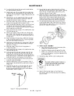
32. Install bearing cap (27) in outboard head (23) without
capscrews. Press bearing cap into head by hand.
Measure gap between bearing cap (27) and outboard
head surface. Refer to Figure 11.
Figure 11. Bearing Cap Installation
33. Remove bearing cap and install shims (26) with total
thickness equal to measurement of gap between bearing
cap and head. Reinstall bearing cap, and torque the
capscrews (28) per Torque Table 1.
34. Rotate the shaft by hand to test for binding. If the rotor
does not turn freely, remove bearing cap (27) and install
another 0.005” shim between bearing cap and head.
Check for free rotation of rotor and shaft. Repeat this
procedure, adding more shims until rotor spins freely.
35. If a motor adaptor is being used, mount with the four
mounting bolts (28A) to the head of the pump. Ensure
that the adaptor support ribs are in the 12:00 and 6:00
position with respect to the ground.
36.
RELIEF VALVE ASSEMBLY
a. Insert the valve (9) into the relief valve bore of the
casing with the fluted end inward.
b. Install the relief valve spring (8) against the valve.
c.
Attach a new relief valve O-ring (10) and the valve
cover (4) on the casing. Torque the capscrews (28)
per Torque Table 1.
37. Reinstall coupling, shaft key, and coupling guards.
Operation without guards in place can
cause serious personal injury, major
property damage, or death.
Do not operate
without guard
in place
38. Refer to “Pre-Start Up Check List” and “Start Up
Procedures” sections of this manual prior to restarting
pump operation.


