BLACKMER LGL154A Скачать руководство пользователя страница 3


501-K00    Page 3/12 

INSTALLATION 


NOTICE: 

Blackmer pumps must only be installed in systems 
designed by qualified engineering personnel.  System 
design must conform with all applicable regulations and 
codes and provide warning of all system hazards. 


NOTICE: 

This pump shall be installed in accordance with the 
requirements of NFPA 58 all applicable local, state and 
national regulations. 


  Install, ground and wire to local and 

National Electrical Code requirements. 

  Install an all-leg disconnect switch near 

the unit motor. 

  Disconnect and lockout electrical power 

before installation or service 


Electrical supply MUST match motor 
nameplate specifications. 

Hazardous voltage. 

Can shock, burn or 

cause death. 

  Motors equipped with thermal protection automatically 

disconnect motor electrical circuit when overload exists.  
Motor can start unexpectedly and without warning. 


PRE-INSTALLATION CLEANING 

NOTICE: 

New pumps contain residual test fluid and rust inhibitor.  
If necessary, flush pump prior to use. 

 
Foreign matter entering the pump WILL cause extensive 
damage.  The supply tank and intake piping MUST be 
cleaned and flushed prior to pump installation and operation. 
 

LOCATION AND PIPING 

Pump life and performance will be significantly reduced when 
installed in an improperly designed system. Before starting 
the layout and installation of the piping system, review the 
following suggestions: 

1.  Locate the pump as near as possible to the source of 

supply to avoid excessive inlet pipe friction. 

2.  The inlet piping and fittings should be at least as large as 

the intake port on the pump. It should slope downward to 
the pump, and should not contain any upward loops. 
Minimize the number of intake line fittings and eliminate 
restrictions such as sharp bends; globe valves, 
unnecessary elbows, and undersized strainers. 

3.  A strainer must be installed in the inlet line to protect the 

pump from foreign matter. The strainer should be located 
at least 24" (0.6m) from the pump, and have a net open 
area of at least four times the area of the intake piping. 
Strainers must be cleaned regularly to avoid pump 
starvation.  (Strainers are optional when pumping from 
underground tanks.) 

4.  The intake and discharge piping system must be free of 

all leaks. 

5.  Expansion joints, placed at least 36" (0.9m) from the 

pump, will compensate for expansion and contraction of 
the pipes. Contact the flexible connector/hose 
manufacturer for required maintenance/care and design 
assistance in their use. 

6. 

ALL piping and fittings MUST be properly supported to 
prevent any piping loads from being placed on the pump. 


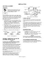
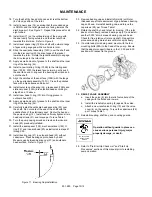
7.  Check alignment of pipes to pump to avoid strains which 

might later cause misalignment.  See Figure 1.  Unbolt 
flanges or break union joints.  Pipes should not spring 
away or drop down.  After pump has been in operation 
for a week or two, completely recheck alignment. 


Figure 1 

8.  Install pressure gauges in the NPT ports provided in the 

pump casing to check pump performance at start up. 

9.  The use of a 1.5” or 2” vapor return line will speed 

delivery by preventing pressure build up at the receiving 
tank and pressure reduction in the supply tank. 

10.  Keeping the liquefied gas systems full of liquid, even 

when idle, will keep the O-rings from changing shape, 
shrinking or super cooling. Evaporation of liquefied gas 
leaves an abrasive powder on the surface which can 
cause wear to the pump, meter, and seals. 


PUMP MOUNTING 

Permanently mount the unit by securing the base plate with 
adequately sized anchor bolts to a level concrete floor 
following recommended industry standards (See Figure 2).  A 
solid foundation will reduce system noise and vibration, and 
will improve pump performance.  Refer to ANSI/HI standards 
or a suitable pump handbook for information on typical pump 
mounting and foundations.  Check coupling alignment after 
pump and base assembly is secured to the foundation. 

BOLT

BASE

STANDARD

PIPE

WASHER


Figure 2.  Foundation Anchor 

When installing units built on channel or structural steel type 
bases, use care to avoid twisting the base out of shape when 
anchor bolts are tightened. Shims should be used under the 
edges of the base prior to tightening of the anchor bolts to 
prevent distortion. 
 

Содержание LGL154A

Страница 1: ...s a SAFETY ALERT SYMBOL When you see this symbol on the product or in the manual look for one of the following signal words and be alert to the potential for personal injury death or major property damage Warns of hazards that WILL cause serious personal injury death or major property damage Warns of hazards that CAN cause serious personal injury death or major property damage Warns of hazards tha...

Страница 2: ...ath Hazardous or toxic fluids can cause serious injury Do not operate without guard in place PUMP DATA PUMP IDENTIFICATION A pump Identification tag containing the pump serial number I D number and model designation is attached to each pump It is recommended that the data from this tag be recorded and filed for future reference If replacement parts are needed or if information pertaining to the pu...

Страница 3: ...at least four times the area of the intake piping Strainers must be cleaned regularly to avoid pump starvation Strainers are optional when pumping from underground tanks 4 The intake and discharge piping system must be free of all leaks 5 Expansion joints placed at least 36 0 9m from the pump will compensate for expansion and contraction of the pipes Contact the flexible connector hose manufacture...

Страница 4: ...pe the bypass valve back to the intake line The setting on the external bypass valve should be at least 25 PSI 1 7 bar lower than the internal pump relief valve setting The valve and piping must be of adequate size to accommodate the full flow from the pump when the discharge line is closed The non adjustable pump internal relief valve is factory set at approximately 225 PSI 15 5 bar A Blackmer Mo...

Страница 5: ...Install the pump directly over the tank and as close to the ground as possible Minimize the Number of Fittings Every fitting valve and piece of straight piping causes a pressure drop and adds to the startup vapor volume Use a minimum number of fittings on the inlet side of the pump Eliminate all possible elbows in the inlet piping by moving the pump so that they will not be necessary Size the inle...

Страница 6: ...t reverse rotation of motor START UP PROCEDURES NOTICE Consult the Troubleshooting section of this manual if difficulties during start up are experienced 1 Start the motor Priming should occur within one minute 2 Check the pressure gauges to ensure the system is operating within expected parameters Record the gauge readings in the Initial Start Up Information section of this manual for future refe...

Страница 7: ...nted in this manual Torque Table 1 Head Casing Capscrews 21 Ft lbs 30 N m 40 7 Relief Valve Cover Capscrews Ft lbs 20 N m 27 Bearing Cap Capcrews 28 Ft lbs 20 N m 27 STRAINERS Strainers must be cleaned regularly to avoid pump starvation Schedule will depend upon the application and conditions LUBRICATION NOTICE To avoid possible entanglement in moving parts do not lubricate pump bearings hydraulic...

Страница 8: ... pull the rotating seal assembly consisting of seal jacket 153C rotating seal face and rotating O ring 153B 153E from the shaft Remove and discard the rotating O ring 153E 5 Carefully remove the disc 71 6 Remove seal spacer ring 159 from shaft 7 Clean inboard end of pump shaft thoroughly making sure the shaft is free of nicks and burrs This will prevent damage to the mechanical seal and grease sea...

Страница 9: ...de of head with spring and lip side facing inside of head 8 Install bearing spring 24C in inboard head 20 9 Install outer race of bearing 24 into bearing pocket in inboard head 20 10 Install grease seal 104A into bearing pocket of head with open side toward bearing and flat side facing outward Gently push or tap the grease seal until flat face of grease seal is about 1 8 4 mm past the larger diame...

Страница 10: ...ionary seat Center the head on the pump casing 12 Install and uniformly tighten all six head capscrews 21 and torque per Torque Table 1 30 Turn the pump casing around and remove the inboard head 20 previously installed 31 Install the seal spacer 159 mechanical seal 153 O ring 72 and inboard head 20 as instructed in steps 21 through 29 32 Install bearing cap 27 in outboard head 23 without capscrews...

Страница 11: ...ed discharge line 3 Pump not securely mounted 4 Improper drive line truck mounted pumps See Pump Drive 5 Misalignment of pump reducer or motor base mounted pumps 6 Bearings worn or damaged 7 Vibration from improperly anchored piping 8 Bent shaft or drive coupling misaligned 9 Excessively worn rotor 10 Malfunctioning valve in the system 11 Relief valve setting too low 12 Liner installed backwards 1...

Страница 12: ...rifugal Pumps 10 to 7500 GPM Process Marine Magnetic Drive Pumps Stainless Steel 14 to 215 GPM Abaque Peristaltic Hose Pumps 0 1 to 210 GPM High Lift Solids Abrasives Reciprocating Gas Compressors Liquefied Gas Transfer Boosting Vapor Recovery Hand Operated Pumps Dispensing Transfer In line Accessories Gear Reducers Bypass Valves Strainers Visit www blackmer com for complete information on all Bla...

Отзывы: