background image


501-K00    Page 4/12 

INSTALLATION 


COUPLING ALIGNMENT 


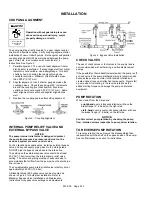
Operation without guards in place can 
cause serious personal injury, major 
property damage, or death. 


Do not operate 

without guard  

in place


The pump must be directly coupled to a gear reducer and/or 
driver with a flexible coupling.  Verify coupling alignment after 
installation of new or rebuilt pumps.  Both angular and parallel 
coupling alignment MUST be maintained between the pump, 
gear, motor, etc. in accordance with manufacturer’s 
instructions. See Figure 3. 

1.  Parallel alignment:  The use of a laser alignment tool or 

dial indicator is preferred.  If a laser alignment tool or dial 
indicator is not available, use a straightedge.  Turn both 
shafts by hand, checking the reading through one 
complete revolution.  Maximum offset should be less 
than .0005" (0.127 mm). 

2.  Angular alignment:  Insert a feeler gauge between the 

coupling halves.  Check the spacing at 90° increments 
around the coupling (four checkpoints).  Maximum 
variation should not exceed 0.005" (0.127 mm).  Some 
laser alignment tools will check angular alignment as 
well. 

3.  Replace the coupling guards after setting alignment. 


Figure 3 – Coupling Alignment 


INTERNAL PUMP RELIEF VALVE AND 
EXTERNAL BYPASS VALVE 

NOTICE: 

The pump internal relief valve is designed to protect 
the pump from excessive pressure and must not be 
used as a system pressure control valve. 

For ALL liquefied gas applications, install an external bypass 
valve, and any necessary piping, back to the storage tank.  
DO NOT pipe the bypass valve back to the intake line.   

The setting on the external bypass valve should be at least 
25 PSI (1.7 bar) lower than the internal pump relief valve 
setting.  The valve and piping must be of adequate size to 
accommodate the full flow from the pump when the discharge 
line is closed. 

The non-adjustable pump internal relief valve is factory set at 
approximately 225 PSI (15.5 bar). 

A Blackmer Model BV bypass valve can be mounted as 
shown in Figure 4 for bulk plant installation. Refer to 
Blackmer Bypass Valve Installation and Maintenance 
Instructions for bypass valve settings and adjustments. 


Figure 4.  Bypass Valve Installation 


CHECK VALVES 


The use of check valves or foot valves in the supply tank is 
not recommended with self-priming, positive displacement 
pumps.  


If the possibility of liquid backflow exists when the pump is off, 
a check valve in the pump discharge piping is recommended 
because the pump can motor in the reverse rotation and 
create undue stress on all attached components.  Never start 
a pump when it is rotating in the reverse rotation as the 
added starting torque can damage the pump and related 
equipment. 


PUMP ROTATION 

When viewed from the driven end: 

right-hand 

pump (clockwise rotation) will have the 

intake flange (2”, 8 bolts) on the right side. 

left -hand 

pump (counter-clockwise rotation) will have 

the intake flange (2”, 8 bolts) on the left side. 

NOTICE: 

Confirm correct pump rotation by checking the pump 
flow / rotation arrows respective to pump driver rotation. 


TO REVERSE PUMP ROTATION 

To reverse rotation, the pump must be disassembled then 
reassembled with the shaft on the opposite side of the pump.  
See the ‘Maintenance’ section for instructions. 
 

Содержание LGL154A

Страница 1: ...s a SAFETY ALERT SYMBOL When you see this symbol on the product or in the manual look for one of the following signal words and be alert to the potential for personal injury death or major property damage Warns of hazards that WILL cause serious personal injury death or major property damage Warns of hazards that CAN cause serious personal injury death or major property damage Warns of hazards tha...

Страница 2: ...ath Hazardous or toxic fluids can cause serious injury Do not operate without guard in place PUMP DATA PUMP IDENTIFICATION A pump Identification tag containing the pump serial number I D number and model designation is attached to each pump It is recommended that the data from this tag be recorded and filed for future reference If replacement parts are needed or if information pertaining to the pu...

Страница 3: ...at least four times the area of the intake piping Strainers must be cleaned regularly to avoid pump starvation Strainers are optional when pumping from underground tanks 4 The intake and discharge piping system must be free of all leaks 5 Expansion joints placed at least 36 0 9m from the pump will compensate for expansion and contraction of the pipes Contact the flexible connector hose manufacture...

Страница 4: ...pe the bypass valve back to the intake line The setting on the external bypass valve should be at least 25 PSI 1 7 bar lower than the internal pump relief valve setting The valve and piping must be of adequate size to accommodate the full flow from the pump when the discharge line is closed The non adjustable pump internal relief valve is factory set at approximately 225 PSI 15 5 bar A Blackmer Mo...

Страница 5: ...Install the pump directly over the tank and as close to the ground as possible Minimize the Number of Fittings Every fitting valve and piece of straight piping causes a pressure drop and adds to the startup vapor volume Use a minimum number of fittings on the inlet side of the pump Eliminate all possible elbows in the inlet piping by moving the pump so that they will not be necessary Size the inle...

Страница 6: ...t reverse rotation of motor START UP PROCEDURES NOTICE Consult the Troubleshooting section of this manual if difficulties during start up are experienced 1 Start the motor Priming should occur within one minute 2 Check the pressure gauges to ensure the system is operating within expected parameters Record the gauge readings in the Initial Start Up Information section of this manual for future refe...

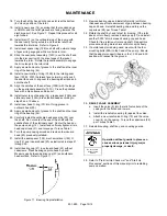
Страница 7: ...nted in this manual Torque Table 1 Head Casing Capscrews 21 Ft lbs 30 N m 40 7 Relief Valve Cover Capscrews Ft lbs 20 N m 27 Bearing Cap Capcrews 28 Ft lbs 20 N m 27 STRAINERS Strainers must be cleaned regularly to avoid pump starvation Schedule will depend upon the application and conditions LUBRICATION NOTICE To avoid possible entanglement in moving parts do not lubricate pump bearings hydraulic...

Страница 8: ... pull the rotating seal assembly consisting of seal jacket 153C rotating seal face and rotating O ring 153B 153E from the shaft Remove and discard the rotating O ring 153E 5 Carefully remove the disc 71 6 Remove seal spacer ring 159 from shaft 7 Clean inboard end of pump shaft thoroughly making sure the shaft is free of nicks and burrs This will prevent damage to the mechanical seal and grease sea...

Страница 9: ...de of head with spring and lip side facing inside of head 8 Install bearing spring 24C in inboard head 20 9 Install outer race of bearing 24 into bearing pocket in inboard head 20 10 Install grease seal 104A into bearing pocket of head with open side toward bearing and flat side facing outward Gently push or tap the grease seal until flat face of grease seal is about 1 8 4 mm past the larger diame...

Страница 10: ...ionary seat Center the head on the pump casing 12 Install and uniformly tighten all six head capscrews 21 and torque per Torque Table 1 30 Turn the pump casing around and remove the inboard head 20 previously installed 31 Install the seal spacer 159 mechanical seal 153 O ring 72 and inboard head 20 as instructed in steps 21 through 29 32 Install bearing cap 27 in outboard head 23 without capscrews...

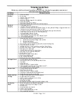
Страница 11: ...ed discharge line 3 Pump not securely mounted 4 Improper drive line truck mounted pumps See Pump Drive 5 Misalignment of pump reducer or motor base mounted pumps 6 Bearings worn or damaged 7 Vibration from improperly anchored piping 8 Bent shaft or drive coupling misaligned 9 Excessively worn rotor 10 Malfunctioning valve in the system 11 Relief valve setting too low 12 Liner installed backwards 1...

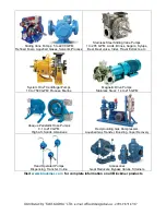
Страница 12: ...rifugal Pumps 10 to 7500 GPM Process Marine Magnetic Drive Pumps Stainless Steel 14 to 215 GPM Abaque Peristaltic Hose Pumps 0 1 to 210 GPM High Lift Solids Abrasives Reciprocating Gas Compressors Liquefied Gas Transfer Boosting Vapor Recovery Hand Operated Pumps Dispensing Transfer In line Accessories Gear Reducers Bypass Valves Strainers Visit www blackmer com for complete information on all Bla...

Отзывы: