background image

ACX4000 

24 

8.


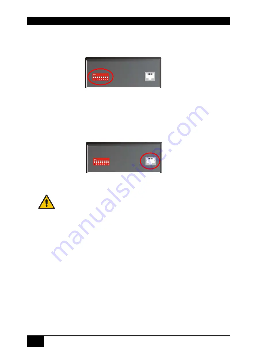
Set the DIP-switches to the positions which correspond to your desired application. 
Information for the DIP switch set-up can be found under 

Operating Mode Selection 

9.


on page

 43.


10.


Depending upon your application, it may be necessary to make a connection to a 
controller over the serial interface. Attach the provided RJ45 to DSUB 9-pin cable at the 
socket of the serial interface and connect it with your controller. More information for 
control through the serial interface can be found on pages 55, 65 or 75. 


11.


Connect the 5V power supplies to the units. 

Only use the power supply originally supplied with this 
equipment or a manufacturer-approved replacement. 

12.


For a dual access system, connect the monitor for the local console to the appropriate 
port on the Local Unit. The port may also be used to feed into a KVM switch. 
 
To attach a local (USB-) keyboard/mouse, please use additional USB port(s) at your 
CPU or use a USB hub between the CPU and Local Unit’s USB- connector. 

13.


Power up the system. 


Содержание ACX4000

Страница 1: ...ACX4000 DVI D CatX Multiplex Repeater Cross point Switch Single head KVM Switch Dual head KVM Switch Manual http www blackbox com...

Страница 2: ...be switched in turn to a single display The changeover can be triggered remotely using the serial interface RS232 and or by a push button at the device As a 7 port KVM Switch up to 7 Single head port...

Страница 3: ...t For an introduction to the Converter see Chapter 2 The Converter product codes covered in this manual are ACX4000 7 port Switch ACS4100A T ACX4000 DVI only Local Unit ACS4122A T ACX4000 DVI serial a...

Страница 4: ...acturer assume any liability for damages resulting from the use of the information contained herein The manufacturer reserves the right to change the specifications functions or circuitry of the produ...

Страница 5: ...LEERE SEITE 5...

Страница 6: ...IEC 61000 4 3 2001 IEC 61000 4 4 2001 EN 61000 3 2 2001 EN 61000 3 3 2002 The device was tested in a typical configuration with CPU This equipment has been found to comply with the limits for a Class...

Страница 7: ...t any airflow Do not place a power supply directly on top of a unit Do not obscure a unit s ventilation holes To safeguard against personal injury and avoid possible damage to equipment or property pl...

Страница 8: ...tch for CATx 26 Configuration Multiplex Repeater 1 Source up to 7 Displays 26 Configuration Multiplex Repeater 2 Sources each up to 3 Displays 26 Configuration Multiplex Repeater 4 Sources on 4 Displa...

Страница 9: ...ostic LEDs 53 Setup 54 Operation 54 By serial interface 54 Control commands 54 7 2 Cross point Switch 55 Configuration Cross point Switch 1 Input 7 Outputs 56 Configuration Cross point Switch 2 Inputs...

Страница 10: ...ructions within the command mode 83 Examples 84 7 5 Systeminfo 85 Control command 85 Available Information 85 7 6 Restore Factory Defaults 86 8 Troubleshooting 87 Monitor 87 USB Keyboard USB Mouse 88...

Страница 11: ...d Shipping Weight 108 Environmental 109 B ACX4000 Switch Unit 110 Power Supply 110 Interface 110 Maximum Length of Interconnection Cable 110 Type of Interconnection Cable 110 Size and Shipping Weight...

Страница 12: ...4000 SWITCH with the help of the provided stickers according to your application 2 Set the DIP switch according to your application 3 Connect ACX4000 Switch to Local unit with CATx cable s 4 Connect A...

Страница 13: ...tively signals coming from 7 signal sources can be switched in turn to a display The changeover can be triggered remotely using the serial interface RS232 and or by a push button at the device As a 7...

Страница 14: ...ts one Monitor Keyboard Mouse Dual head An extender system that supports two Monitors Keyboard Mouse DVI Digital Video standard installed by Digital Display Working Group www ddwg org R G B CLOCK in a...

Страница 15: ...le application for a ACX4000 Switch System Multiplex Repeater or Cross point Switch Up to 7 remote monitors and audio outputs CPU with DVI graphic card and audio output ACX4000 Extender Local Unit Loc...

Страница 16: ...ard mouse and touch screen simultaneously You can extend a USB hub but this does not raise the number of supported devices Maximum length of interconnection cable from a Local Unit to a ACX4000 Switch...

Страница 17: ...l Unit Dual head ACS4022A T ACX4000 DVI USB HID serial Audio Local Unit Single head ACS4222A T ACX4000 DVI USB HID serial Audio Local Unit Dual head KVM Extender DVI USB HID optional serial audio Remo...

Страница 18: ...e Compatible with all standard 2 button 3 button and wheel mice The ACX4000 KVM devices with USB connectors support the extension of keyboard and mouse ONLY use with other HID devices Human Interface...

Страница 19: ...Unit Page 46 Selecting the moment of switching to the next frame The transmission of screen data is not synchronous to the screen changes of the graphic card Normally the transmission is terminated d...

Страница 20: ...package ACX4000 Switch 1x 5V DC universal power supply for the ACX4000 Switch 1x serial cable RJ45 DB9 Female for switching purpose 1x US type power cord 1x sheet of product stickers User manual Quick...

Страница 21: ...ces audio 1x Serial link audio ZIP type cable 1 8m with one side DSUB9pin female connector 2x 3 5mm stereo plugs other side miniDIN8pin male connector The following parts should be in your ACX4000 KVM...

Страница 22: ...ATx cable Recommended cable S UTP Cat5 according EIA TIA 56A TSB 36 or Digital STP 17 03170 Four pairs AWG 24 Wiring according EIA TIA 568A 10BaseT Use of cables from a higher category Cat5e Cat6 Cat7...

Страница 23: ...etween the ACX4000 switch and Local Unit and between the ACX4000 switch and Remote Unit Use for this either the provided crossed CATx cable or insert the provided crossed cable with the help of the pr...

Страница 24: ...t it with your controller More information for control through the serial interface can be found on pages 55 65 or 75 11 Connect the 5V power supplies to the units Only use the power supply originally...

Страница 25: ...d or mounting parts If mounted into 19 racks the space to the left and to the right side of the ACX4000 must kept free The ACX4000 Switch its extenders and power supplies may become warm Do not instal...

Страница 26: ...o the ACX4000 Media Remote Units Push button no function in this operating mode Push button no function in this operating mode R L R R R R R R Connect to the ACX4000 Media Local Unit Connect to the AC...

Страница 27: ...tch 1x7 Connect to 5V power supply Push button no function in this operating mode LA LB LD LC RA RB RD RC Connect to the ACX4000 KVM Media Local Units Connect to the ACX4000 KVM Media Remote Units R1...

Страница 28: ...R2 R1 R6 L1 L2 Push button for the sequential selection of pre programmed configurations Connect to 5V power supply Connect to the ACX4000 Media Local Units Connect to the ACX4000 Media Remote Units L...

Страница 29: ...tton for the sequential selection of pre programmed configurations Connect to 5V power supply L4 L1 L2 L3 R2 R4 R3 R1 Pushbutton for the sequential selection of pre programmed configurations Connect t...

Страница 30: ...o 5V power supply L4 L1 L2 L3 R2 R1 L5 L6 Pushbutton for the sequential selection of pre programmed configurations Connect to 5V power supply Connect to the ACX4000 Media Local Units Connect to the AC...

Страница 31: ...K M Connect to the ACX4000 KVM Remote Units Console Video 1 K M L4 L1 L2 L3 R L5 L6 L7 Connect to 5V power supply Connect to the ACX4000 KVM Local Units CPU Push button for the sequential selection o...

Страница 32: ...ACX4000 32 ACX4000 Switch rear view Serial Interface RS232 Operating Mode DIP switch...

Страница 33: ...CX4000 Media Local Unit ACX4000 Media Remote Unit ACX4000 Media Local Unit with Audio To CPU DVI Connect to remote DVI monitor Connect to local DVI monitor Connect to CPU DVI graphic card Local DVI mo...

Страница 34: ...Audio ACX4000 Media Local Remote Unit rear view Audio Out Connect to 5V power supply Remote DVI monitor port connect to remote console monitor Serial Out INTERCONNECT carries video and data signals co...

Страница 35: ...Local Remote Unit rear view Connect to 5V power supply Remote keyboard mouse port To CPU DVI graphic card Connect to local DVI monitor INTERCONNECT carries video and data signals connect to Local Remo...

Страница 36: ...with audio ACX4000 KVM Remote Unit with Audio Audio In To CPU Serial To CPU DVI Connect to CPU USB Audio Out Serial Out Connect to local DVI monitor Remote DVI monitor port Connect to remote console m...

Страница 37: ...hic card 2 nd local DVI monitor port Connect to local console 2 nd monitor Connect to CPU 1 st DVI graphic card Local DVI monitor port Connect to local console monitor 2 nd remote DVI monitor port Con...

Страница 38: ...rt Connect to remote console 2 nd monitor 1 st remote DVI monitor port Connect to remote console 1 st monitor Connect to CPU 2 nd DVI Graphic card 2 nd local DVI Monitor port Connect to Local console...

Страница 39: ...o rear view Connect to 5V power supply Connect to 5V power supply INTERCONNECT carries 2 nd video Connect to Local Remote Unit with CATx cable INTERCONNECT carries 1 st video and data signals Connect...

Страница 40: ...ch for CATx LED Appearance Diagnostics Power LED Red LED Off On Device not ready Device ready Link Status Green Orange LED Off Orange ON Orange blinking Green ON Green blinking No transmission over th...

Страница 41: ...rance Diagnostics Power LED Red LED Off On Device not ready Device ready Video Okay Green LED Off On No or invalid video signal detected Device ready Link Status Green LED blinking On No CATx connecti...

Страница 42: ...tputs may be changed In doing so it is possible to interconnect two transmitters this may damage the connected equipment The location of the operating mode selector DIP switch is shown below For the s...

Страница 43: ...Switch Every port can either be an input to a Local Unit or an output to a Remote Unit Each connection input output is possible 1x IN 7x OUT The signals of one source can be switched to up to 7 displ...

Страница 44: ...2 set the DIP switch 3 switch power on the device is resetting 4 switch power off 5 set the DIP switch back 6 switch power on done Operating Mode after Reset Power ON After reset the respective DEFAUL...

Страница 45: ...ws at both sides at the bottom of the device Unscrew the UNC type screws on each side of the monitor connectors Carefully displace the lower and upper shells of the case The following diagnostic LEDs...

Страница 46: ...locate jumpers DDC colour depth You can select whether the DDC information is taken from internal DDC table from the local monitor or downloaded from the remote monitor and stored in internal table D...

Страница 47: ...ocal Unit and stored into the DDC EPROM After a successful programming of the DDC EPROM the Video OK LED at the Local Unit is blinking rapidly for approx 1 second Done Selection of Color depth You can...

Страница 48: ...s terminated when a frame is displayed on the screen If the device switches to the new frame during HSYNC the displaying period of the old frame you may see horizontal screen breaks at the moment of s...

Страница 49: ...connected to the second stage repeaters allowing up to 49 display units to be headed The distance between a Local Unit and ACX4000 Switch or between a ACX4000 Switch and Remote Unit or between two ACX...

Страница 50: ...e transferred over CATx cables to one equivalent Remote Unit This allows an extension to the cable length if the usual 140m distance by CATx cables is not sufficient Connect to 5V power supply Input t...

Страница 51: ...OPERATING MODES 51 Example Applications A video audio source is switched over the ACX4000 Switch to 4 different screens loudspeakers Additionally a control monitor can be attached at the Local Unit...

Страница 52: ...ACX4000 52 Three cascaded ACX4000 Switches each with a local second screen and 13 screens for presentations...

Страница 53: ...ng mode Meaning of the diagnostic LEDs OFF Channel not busy appropriate Local Remote Unit is switched off or interconnection cable disconnected ON Green Channel is busy and the connection to the Local...

Страница 54: ...B9 to the CPU is included in delivery For the complete communication protocol and an explanation of the control characters please see Appendix D Protocol for command mode For communication please set...

Страница 55: ...CX4000 Switch the transmission continues over CATx cables to up to 7 Remote Units Alternatively a further ACX4000 Switch slave can be used between the first stage switch and further Remote Units There...

Страница 56: ...o 6 outputs and transferred over CATx cables to 6 Remote Units Optionally a further ACX4000 Switch can be inserted for a second switching stage R1 R3 R2 R4 R5 R6 R7 L Connect to the ACX4000 Media Remo...

Страница 57: ...to 4 outputs and transferred over CATx cables to 4 Remote Units Optionally a further ACX4000 Switch can be inserted for a second switching stage L1 L2 L3 R2 R4 R5 R3 R1 Connect to the ACX4000 Media R...

Страница 58: ...to 2 outputs also on several and be transferred over CATx cables on up to 2 Remote Units Optionally a further ACX4000 Switch can be inserted for a second switching stage Push button for the sequentia...

Страница 59: ...transferred over CATx cables to one Remote Unit Optionally a further ACX4000 Switch can be inserted for a second switching stage Connect to 5V power supply L4 L1 L2 L3 L5 L6 L7 Connect to the ACX4000...

Страница 60: ...ACX4000 60 Example Application Three video sources are switched over the ACX4000 Switch on four different screens...

Страница 61: ...he respective DEFAULT Mode is selected 1x7 Input I1 is switched to Output O1 2x6 I1 to O1 and I2 to O2 3x5 I1 to O1 I2 to O2 and I3 to O3 4x4 I1 to O1 I2 to O2 I3 to O3 and I4 to O4 5x3 I1 to O1 I2 to...

Страница 62: ...busy appropriate Local Remote Unit is switched off or interconnection cable disconnected BLINKING Green Channel of the current selected CPUs BLINKING Orange Selection of an inactive channel ON Green...

Страница 63: ...perated for longer than 2 seconds With the first key press the macro display is switched on The LED with the number of the active selected macro flashes With each key press the display will switch to...

Страница 64: ...TX 0x54 ETX Reset the switch and set the connections as a function of SW7 see above STX 0x40 0x80 ETX Read the system info version number from the switch STX 0x52 ETX Switch off all local remote conne...

Страница 65: ...ascading of the ACX4000 KVM Switch in two stages is in all application areas allowed so up to 49 CPUs to be addressed In addition to the DVI signals and USB for keyboard mouse bi directional stereo au...

Страница 66: ...ACX4000 66 Example Application Four CPUs are switched over the ACX4000 Switch to one console...

Страница 67: ...ACX4000 KVM Switches are cascaded it is on the highest level directly after the console The device is Slave if ACX4000 KVM Switches are cascaded it is on second level directly after the Local Units O...

Страница 68: ...appropriate Local Remote Unit is switched off or the interconnection cable is disconnected BLINKING Green Channel of the current selected CPUs BLINKING Orange Selection of an inactive channel ON Green...

Страница 69: ...ess the display will switch to the next channel as indicated by a rapidly blinking LED If the last channel is reached the device will cycle to the first channel b By serial interface You can find the...

Страница 70: ...tatus from macro where Loc No 7Bit date 1 to 7 Macro No 7Bit date 1 to 8 Examples STX 0x54 ETX Reset the switch and set the connections as a function of SW7 see above STX 0x40 0x80 ETX Read the system...

Страница 71: ...put of letters does not differentiate between large and lower case SHIFT shifts between upper and lower case Key1 Key2 means that all keys must be pressed at the same time Key1 Key2 means that the key...

Страница 72: ...delivery status 1 1 CTRL SHIFT I simultaneous 2 Scroll lock Scroll lock press twice rapidly 3 left SHIFT left SHIFT press twice rapidly 4 left CTRL left CTRL press twice rapidly 5 left ALT left ALT pr...

Страница 73: ...mber of the port Caution Applies only to the selected level M x S y RETURN or M 0 x S 0 y RETURN Only in cascaded applications Switch the master to port 0x and the attached slave on port 0y with x and...

Страница 74: ...to 7 y ASCII digits 1 to 7 Examples CTRL SHIFT I Call the command mode SHIFT 3 Switch immediately to port 3 after call the master is selected M2S5 RETURN Switch the master to port 2 and the slave to...

Страница 75: ...tages for all applications allowing up to 9 dual head CPUs to be addressed In addition to the DVI signals and USB for keyboard mouse bi directional stereo audio serial RS232 V24 can be transferred by...

Страница 76: ...ACX4000 76 Example Application Three CPUs with dual head graphic cards and local consoles switched over the ACX4000 Switch to one console...

Страница 77: ...if ACX4000 KVM Switches are cascaded it is on highest level directly after the console The device is slave if ACX4000 KVM Switches are cascaded it is on second level directly after the Local Units Op...

Страница 78: ...y or appropriate Local Remote Unit is switched off or the interconnection cable is disconnected BLINKING Green Channel of the current selected CPUs BLINKING Orange Selection of an inactive channel ON...

Страница 79: ...ess the display will switch to the next channel indicated by a rapidly blinking LED If the last channel is reached the device will switch to the first channel b By serial interface You can find the al...

Страница 80: ...Examples STX 0x54 ETX Reset the switch and set the connections as a function of SW7 see above STX 0x40 0x80 ETX Read the system info version number from the switch STX 0x47 0x81 0x81 ETX Switch conso...

Страница 81: ...ters does not differentiate between large and lower case SHIFT shifts between upper and lower case Key1 Key2 means that all keys must be pressed at the same time Key1 Key2 means that the keys must be...

Страница 82: ...delivery status 1 1 CTRL SHIFT I simultaneous 2 Scroll lock Scroll lock press twice rapidly 3 left SHIFT left SHIFT press twice rapidly 4 left CTRL left CTRL press twice rapidly 5 left ALT left ALT pr...

Страница 83: ...mber of the port Caution Applies only to the selected level M x S y RETURN or M 0 x S 0 y RETURN Only in cascaded applications Switch the master to port 0x and the attached slave on Port 0y with x and...

Страница 84: ...y ASCII digits 1 to 3 Examples CTRL SHIFT I Call the command mode SHIFT 3 Switch immediately to port 3 after call the master is selected M2S1 RETURN Switch the master to port 2 and the slave to 1 3 R...

Страница 85: ...cable RJ45 on DB9 to a CPU is included in delivery For communication please set up the format of the serial data communication to 115 2K 8 1 NO 115 2 KBAUD 8 Data bit 1 Stop bit NO parity Control comm...

Страница 86: ...e In the Cross point Switch operating mode all macros in memory are reset Standard operating mode Reset the ACX4000 Switch to default settings Factory Reset 1 switch power off 2 set the DIP switch 3 s...

Страница 87: ...tted each second expires the capability of the data link Therefore the data have to be reduced before transmitting This is done in a first step by a so called RLE Run Length Encoding algorithm If this...

Страница 88: ...Depending to our measurements a delay of approx 100 150msec are recognized as disturbing The total delay comes from time values are approx values 5 to 15msec for mouse movement and data transmission t...

Страница 89: ...compression Avoid photos for background or horizontally graduated colors better use monochrome backgrounds They allow higher compression higher frame rates If and only if the link has frame dropping a...

Страница 90: ...ACX4000 90 Appendix A Example Applications This section illustrates some specific applications using the ACX4000 Minor ACX4000 as Multiplex Repeater with audio option...

Страница 91: ...APPENDIX A EXAMPLE APPLICATIONS 91 Three cascaded ACX4000 as Multiplex Repeater and a total of 13 screens for presentations...

Страница 92: ...ACX4000 92 ACX4000 as Cross point Switch here 3x Input 4x Output...

Страница 93: ...APPENDIX A EXAMPLE APPLICATIONS 93 ACX4000 as Single head KVM Switch to 7 1 optional with a local console and or serial audio option...

Страница 94: ...ACX4000 94 ACX4000 as Dual head KVM Switch to 3 1 with a local console...

Страница 95: ...the list of parts delivered allow covering unused device positions Rack mount kit 455 4G List of parts delivered Mounting instruction Align the holes on the base plate with the vacant screw holes on...

Страница 96: ...can mount a rack mountable p s u type 455 PS instead of a regular device This p s u is capable of powering up to three devices Please note Use the rear mounting holes to fix the p s u After mounting t...

Страница 97: ...rts delivered allow covering unused device positions Rack mount kit 455 8G List of parts delivered Mounting instruction Align the holes on the base plate with the vacant screw holes on the base of the...

Страница 98: ...allows mounting of up to 4 devices In the lefthand position you can mount a rack mountable p s u type 455 PS instead of a regular device This p s u is capable of powering up to three devices 19 rack...

Страница 99: ...nit s serial port is wired as DTE i e the same as that on a PC To connect a serial printer or other DTE rather than DCE device to the Remote Unit you will need a Null Modem crossover cable between the...

Страница 100: ...he link Audio Interface Using a Microphone A microphone may be plugged into the Line In connector on the Remote Unit There are two ways of setting up a microphone The Local Unit s Line Out connection...

Страница 101: ...ption Command byte in the range of 0x40 0x6F see the list of allowed commands below Data Bytes a Binary data in order to prevent that during the transmission of binary data control statements or contr...

Страница 102: ...Errors occurred NAK b No errors ACK c Optional reply telegram with data a repeat telegram b next command c receive and process the replay telegram Telegrams global functions Function Telegram Answer 1...

Страница 103: ...UTPUT STX 0x47 INPUT No OUTPUT No ETX ACK 2 switch off a single OUTPUT STX 0x48 OUTPUT No ETX ACK 3 switch a single OUTPUT feedback channel to INPUT STX 0x4B INPUT No OUTPUT No ETX ACK 4 switch off a...

Страница 104: ...ers what type of keyboard brand of mouse make and model of monitor type and make of cable etc Any particular application that when used appears to create the problem or make it worse The results of an...

Страница 105: ...blackbox fr 33 820 07 09 11 33 820 05 07 09 Germany www black box de techsupp black box de 49 811 5541 110 49 811 5541 499 Ireland www blackbox co uk techhelp blackbox co uk 353 1 662 2466 353 1 662...

Страница 106: ...ation is constructed for HID devices HID is a device class enabling inputs to a CPU Touch screens graphic tablets fingerprint sensors are also HID devices Some devices install additional devices e g t...

Страница 107: ...45 1000 Mbit High speed transmission Wiring acc EIA TIA 568B Gigabit Ethernet Audio Interface Description Bi directional stereo audio link Transmission Method Digitized virtually CD quality audio 16 b...

Страница 108: ...ble acc EIA TIA 56A TSB 36 or Digital STP 17 03170 Four pairs AWG 24 Wiring acc EIA TIA 568A 10BaseT CATx patch cable AWG26 8 stranded cable S UTP Cat5 cable acc EIA TIA 56A TSB 36 or Digital STP 17 0...

Страница 109: ...APPENDIX G SPECIFICATIONS 109 Environmental Operating Temperature 41 to 113 F 5 to 45 C Storage Temperature 13 to 140 F 25 to 60 C Relative Humidity max 80 non condensing...

Страница 110: ...Handshake DSR Maximum Length of Interconnection Cable CATx installation cable AWG24 solid cable 140m 400ft CATx patch cable AWG26 8 stranded cable 70m 200ft Type of Interconnection Cable CATx install...

Страница 111: ...00 Switch 103 x 143 x 42mm 4 x5 6 x1 7 Weight 0 6kg 1 3lb Shipping box 460x250x120mm 18 1 x9 8 x4 7 Weight 1 6 kg 3 5lb Environmental Operating Temperature 41 to 113 F 5 to 45 C Storage Temperature 13...

Страница 112: ...a 2 10 T M D S data 1 18 T M D S data 0 3 T M D S data 2 GND 11 T M D S data 1 GND 19 T M D S data 0 GND 4 n c 12 n c 20 n c 5 n c 13 n c 21 n c 6 DDC Input SCL 14 5V high impedance 22 T M D S clock G...

Страница 113: ...ouse connector USB type B Signal Output Local Unit Pin Signal 1 VCC 5V Red 2 Data White 3 Data Green 4 GND Black Keyboard Mouse connector USB type A Signal Output Remote Unit Pin Signal 1 VCC 5V Red 2...

Страница 114: ...ace Single head KVM devices only audio serial option Connector Remote Unit Connector Local Unit Pin Signal Pin Signal 1 n c 1 n c 2 RxD 2 RxD 3 TxD 3 TxD 4 DTR 4 DTR 5 GND 5 GND 6 DSR 6 DSR 7 RTS 7 RT...

Страница 115: ...ctor Audio RS232 Dual head and Media Local Unit only Pin 1 AUDIO GND 2 RS232 GND 3 AUDIO OUT RIGHT CHANEL 4 AUDIO OUT LEFT CHANEL 5 RS232 RxD 6 AUDIO IN RIGHT CHANEL 7 AUDIO IN LEFT CHANEL 8 RS232 TxD...

Страница 116: ...ACX4000 116 B ACX4000 Switch Unit Serial Interface switch socket DCE Pin Pin 1 5V Out 5 TxD Out 2 n c 6 RxD In 3 DSR In 7 n c 4 GND 8 n c 1 8...

Страница 117: ...APPENDIX H CONNECTORS 117 C All ACX4000 Devices Power Supply Pin Signal Inner 5V Outer GND CATx Interfaces Wiring acc EIA TIA 568A 10BaseT Pin Pin 1 D1 5 D3 2 D1 6 D2 3 D2 7 D4 4 D3 8 D4 1 8...

Страница 118: ...118 Appendix I Connection Cable Serial cable to connect the external switchbox to CPU Pin Signal Pin Signal 1 n c 1 5V 2 RxD 2 n c 3 TxD 3 DSR 4 DTR 4 GND 5 GND 5 TxD 6 DSR 6 RxD 7 RTS 7 n c 8 CTS 8 n...

Страница 119: ...NOTES...

Отзывы: