6
7
Connection to Power Source
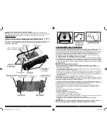
The Power Inverter comes equipped with a DC Accessory Outlet Plug and Battery Clips for connection
to a power source.
CONNECTING TO A POWER SOURCE USING THE DC ACCESSORY OUTLET PLUG (UP TO 100W ONLY)
The DC Accessory Outlet Plug is suitable for operating the inverter at power outputs up to 100 watts
and has overload protection at 100W to prevent you blowing the fuse if you connect a higher rated
appliance. The tip of the plug is positive (+) and the side contact is negative (–).
The opposite end of the DC Accessory Outlet Plug has a unique connector fitted to it which will allow
it to be only fitted into the socket on the rear of the unit when there are NO battery clips connected to
the unit. This is a safety feature and the design of the plug also covers the positive (+) terminal to
prevent both leads being connected at the same time.
• Connect the inverter to the power source by inserting the DC Accessory Outlet Plug firmly into
the accessory outlet of a vehicle or other DC power source. Make sure there is adequate space for
proper ventilation of the inverter.
• Press the translucent on/off button.
• The 100W LED Indicator will light, indicating that the inverter is operating properly and is ready to
power appliances that draw up to 100 watts continuous.
Notes:
If the power/fault LED flashes red, the unit emits three beeps every five seconds, the 100W LED indicator does not light and the AC
and USB outlets shut down, a fault condition has occurred. Refer to the “Troubleshooting” section of this manual.
If the inverter does not work when using the vehicle accessory outlet, make sure the ignition/accessory switch is actually powering
the accessory outlet. Some vehicles require the ignition switch to be turned on.
Ensure that the wattage of all equipment simultaneously plugged into the inverter does not exceed 100 watts continuous
Most vehicle accessory outlet circuits have fuses rated at 15 to 20 amps or greater. To operate at full wattage, either use the battery
clip cable (supplied) or directly wire to the power source with user-supplied wire and fuse.
CAUTIONS
• Connect directly to power source using the included Battery Clips when operating above 100 watts.
• Do not use with positive ground electrical systems.
• Reverse polarity connection will result in a blown fuse and may cause permanent damage to the
inverter.
CONNECTING TO A POWER SOURCE USING THE PROVIDED BATTERY CLIPS WITH SLIDE-IN CONNECTORS
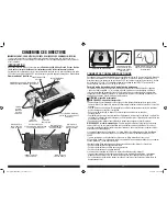
Use the provided Battery Clips (with cables and slide-in connectors) to connect the Power Inverter
directly to the 12 volt power source as follows:
1. Check to make sure the power/fault LED inside the translucent On/Off button is not lit and that no
flammable fumes are present in the installation area.
2. Turn the red plastic cap (counterclockwise) on the inverter’s positive (+) cable post and remove.
Attach the positive connector at the end of the red battery clip cable into the groove of the positive
(+) cable post. Replace the cap and turn clockwise to secure. Do not over-tighten.
3. Turn the black plastic cap (counterclockwise) on the inverter’s negative (–) cable post and remove.
Attach the negative connector at the end of the black battery clip cable into the groove of the
negative (–) cable post. Replace the cap and turn clockwise to secure. Do not over-tighten.
4. Make sure that all connections between cables and terminals are secure.
5. Press the translucent on/off button.
6. The 100W and 500W LED Indicators will light, indicating that the inverter is operating properly and
is ready to power appliances that draw up to 500 watts continuous.
Note:
If the power/fault LED flashes red, the unit emits three beeps every five seconds, the 100W and 500W LED Indicators do not light
and the AC and USB outlets shut down, a fault condition has occurred. Refer to the “Troubleshooting” section of this manual.
DIRECT HARDWIRING TO POWER SOURCE (OPTIONAL CONNECTION METHOD; HARDWARE NOT INCLUDED)
Use #10 AWG wire if the inverter to power source connection is 10 feet or less. For cable lengths up
to 10ft use #8 AWG wire. In either case, protect the positive (+) wire from shorts by installing a 50
amp fuse or circuit breaker close to the DC power source (battery) terminal.
1. Check to make sure the power/fault LED inside the translucent On/Off button is not lit and that no
flammable fumes are present in the installation area.
2. Identify the positive (+) and negative (–) DC power source (battery) terminals.
3. Install a fuse holder or breaker close to the positive (+) terminal of the DC source (battery).
4. Connect a length of wire on one side of the fuse holder or circuit breaker. Connect the other end of
the wire to the positive (+) terminal of the inverter.
Input Voltage Too High — The inverter will automatically shut down when DC input voltage exceeds
16 ± 0.5 volts, as this can harm the unit.
Thermal Shutdown Protection — The inverter will automatically shut down when the unit becomes
overheated.
Overload/Short Circuit Protection — The inverter will automatically shut down when a short circuit
occurs.
OPERATING TIPS
The inverter should only be operated in locations that are:
DRY — Do not allow water or other liquids to come into contact with the inverter.
COOL — Surrounding air temperature should ideally be 10-20°C (50-68°F). Keep the inverter away
from direct sunlight, when possible.
WELL-VENTILATED — Keep the area surrounding the inverter clear to ensure free air circulation
around the unit. Do not place items on or over the inverter during operation. The unit will shut down if
the internal temperature gets too hot. The inverter will auto-reset after it cools down.
SAFE — Do not use the inverter near flammable materials or in any locations that may accumulate
flammable fumes or gases. This is an electrical appliance that can briefly spark when electrical
connections are made or broken.
INSTAllATION
Your inverter will provide you with continuous electrical power when powered by a reliable 12 volt DC
source, such as a vehicle battery or a multiple battery configuration. This manual does not describe all
of the possible configurations.
Mounting the Inverter
Tools Required: four BA4x14 screws in a set and Philips head screwdriver (NOT supplied).
The inverter comes equipped with mounting brackets for long-term installation. The manufacturer
recommends using BA4x14 screws in a set with a standard Philips head screwdriver (none of these
are supplied). User may choose to use different screws appropriate to the mounting surface.
Secure the inverter to a flat surface, observing all cautions regarding installation found in this manual.
CAUTION
To avoid the risk of property damage, only mount the inverter on a level, stable surface, assuring that
all screws are tightened securely and observing all of the cautions and recommendations regarding
installation found in this manual.
Hanging the Inverter
The retractable hanging hook at the bottom of unit allow you to position the inverter for convenient,
hands-free operation.
CAUTION: TO REDUCE THE RISK OF PRODUCT DAMAGE:
• When the hanging hook is not in use, return it to its retracted position.
• When the inverter is hung by the hanging hook, do not shake the unit or the object that it is hanging
from. Do not hang the inverter from any electrical wires, or anything that it is not secure.
• Only use the hanging hook for hanging the inverter. The hanging hook is not intended to support
additional weight. Do not hang anything additional to the inverter or risk of breakage may occur.
OPERATING INSTRUCTIONS
The Power Inverter must be connected only to batteries with a nominal output voltage of 12 volts. The
unit will not operate from a 6 volt battery and will sustain permanent damage if connected to a 24 volt
battery.
The standard North American 120 volt AC outlets and USB charging port allow simultaneous
operation of multiple devices. Simply plug the equipment into the unit and operate normally. Ensure
that the wattage of all equipment simultaneously plugged into the PI500P does not exceed 500 watts
continuous.
CAUTION: TO REDUCE THE RISK OF PROPERTY DAMAGE:
Always connect the PI500P to the 12 volt DC power source before plugging any devices into the unit.
PI500P_ManualEnFrSP_061213.indd 6-7
6/12/2013 6:02:16 PM


