17
Channel Setup
3.1 All Channels Screen
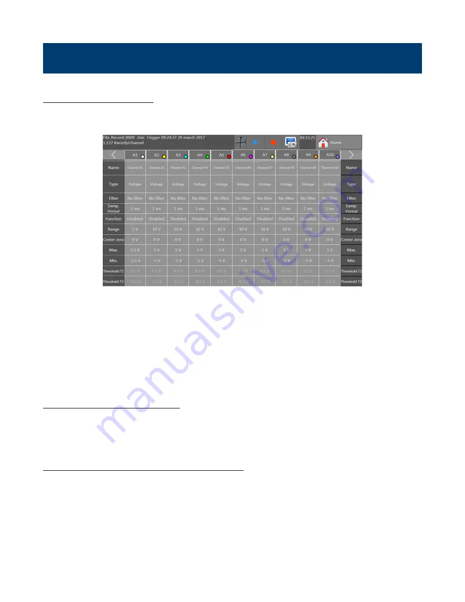
Access the channel setup menu from the Home screen and press the “Channels” button. The screen shown in
appears.
Figure 3.1
Channels Menu
The channel configuration screen provides quick access to individual channel settings. Each column lists a set of values
for each channel. The parameter available is listed in the left and right most columns. Pressing the box corresponding to
the channel and parameter opens a dialog box with options for configuring that parameter. The contents of the dialog
change depending on the selected parameter value. For example, when the channel type parameter is opened, selecting
the Thermocouple value modifies the box to give further options for thermocouples (type, temperature units, etc
…
).
Back on the main channel table, the value in the box shows a summary version of the parameter’s configured value.
In the upper right and left corners of the table are navigation arrows for showing more sets of channels. 10 channels may
be shown on screen at a time.
3.2 Individual Channel Screen
The complete set of parameters, values and options are also viewable for a single channel on a single screen. To open this
screen, press the box displaying the Channel ID (A1 for example). This opens a window for setting a greater number of
values than available from the channels table. For example, the plot color and thickness can be set here. See
3.3 Extension Modules (DAS240-BAT only)
Up to 10 extension modules may be connected at a time.
To assemble multiple terminal block modules:
•
Screw the electrical connectors’ plate to each additional extension
•
Assemble the extension modules together
•
Screw the plates with the adjacent modules
•
Stick the additional adhesive buttress


