background image

8 — EQUIPMENT OPTIONS 
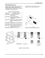
REPLACEMENT DECALS 


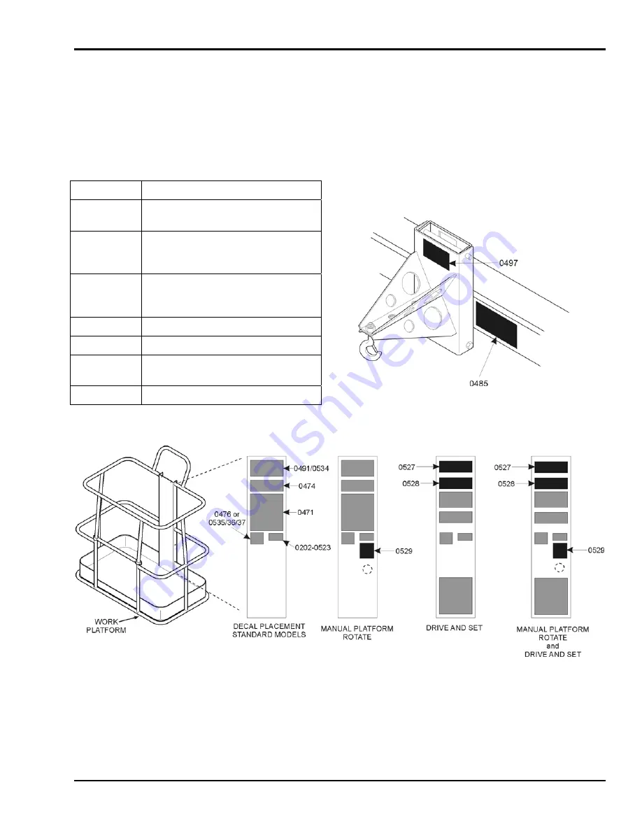
Refer to Table 8-1 and Figure 8-6 to Figure 8-7 for a 
descriptions and locations of replacement decals for 
optional components. Refer to Section 5 for a 
comprehensive list of standard decals on the Bil-Jax 
Model 3632T Telescoping Boom Lift. 

All decals related to optional equipment have a 
quantity of one (1) unless otherwise noted.


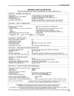
Table 8-1.  Replacement Decals 

Decal No. 

Description of Decal 


51

B06-00-0474  NOTICE: Max. Load (All 

Configurations) 

B06-00-0485 NOTICE: 

Material/Lifting 

Configuration Set-Up (Material Lift 
Option Only) 

B06-00-0497  NOTICE: Load Capacity for Material 

Lifting Hook (Material Lift Option 
Only) 

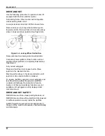
B06-00-0527  WARNING: Drive and Set Hazards 

B06-00-0528  NOTICE: Drive and Set Instruction 

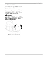
B06-00-0529  NOTICE: Manual Platform Rotation 

(Manual Rotation Option Only) 

B06-00-0553  WARNING: Jockey Wheel 


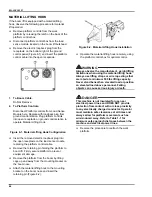
Figure 8-6. Material Lift Decal Placement


Figure 8-7.  Decal Locations

Содержание 3632T

Страница 1: ...OPERATOR S MANUAL T 134 98 B33 01 0089 3632T ...

Страница 2: ...hat only trained and authorized personnel attempt to operate and maintain the boom lift This manual shall be considered a permanent and necessary component of the machine and shall be kept with the boom lift at all times Owners and Lessors should complete a full inspection of all components and perform a test of all functions including brake functions before commissioning or reselling the machine ...

Страница 3: ...Station 14 Platform Control Station 16 Normal Operating Procedure 18 Manual Boom Operations 20 Battery Recharge 22 Boom Lift Transport 23 4 Operator Service 25 Daily Service Checks 26 Weekly Service Checks 28 Monthly Service Checks 29 Troubleshooting 30 Error Code Definitions 31 5 Replacement Decals 33 6 ANSI Reprint 35 7 Material Safety Data 41 8 Equipment Options 45 Material Lifting Hook 46 Plat...

Страница 4: ...sition Switches 26 Figure 4 2 Hydraulic Reservoir 27 Figure 4 3 Wheel Nut Tightening Sequence 29 Figure 5 1 Decal Placements 34 Figure 6 1 Minimum Safe Approach Distances 39 Figure 8 1 Material Lifting Hook Configuration 46 Figure 8 2 Material Lifting Hook Installation 46 Figure 8 3 Manual Platform Rotator 47 Figure 8 4 Jockey Wheel Instruction 48 Figure 8 5 Drive and Set Controls 49 Figure 8 6 Ma...

Страница 5: ...or to Operation Read understand and obey all instructions and safety precautions in this manual and attached to the lift Read understand and obey all applicable government regulations Become familiar with the proper use of all controls Inexperienced users should receive instruction before attempting to operate or maintain the machine The use of intelligence and common sense is the best practice wh...

Страница 6: ...t improper service damage to equipment personal injury or death DANGER Warns of operation near electrical power sources that could lead to personal injury or death WARNING Describes conditions or practices that could lead to personal injury or death CAUTION Contains information important in the prevention of errors that could damage machine or components NOTE Contains additional information import...

Страница 7: ...inal design or operation NEVER deface modify or obscure any decals or markings on equipment NEVER operate the equipment in any way for which it is not intended Ensure the following general safety precautions are followed while operating the telescoping boom lift ALWAYS position lift away from power lines to ensure that no part of the lift can accidentally reach into an unsafe area This includes fu...

Страница 8: ...with materials or personnel on board or while boom is raised or extended NEVER sit stand or climb on cage bars ALWAYS keep both feet firmly on the work cage floor when working from an elevated platform NEVER attempt to increase the working height with boxes ladders stools or any other materials NEVER operate this equipment when exposed to high winds thunderstorms ice or any weather conditions that...

Страница 9: ...ctions NEVER add unauthorized fluids to the hydraulic system or battery NEVER mix hydraulic oils Consult manufacturer specifications Refer to Section 4 for hydraulic system maintenance procedures NEVER exceed the manufacturer s recommended relief valve settings NEVER touch or allow metal tools to contact any components that are sensitive to static discharge ALWAYS use static discharge prevention m...

Страница 10: ...never a Bil Jax lift is damaged structurally or when there is suspected internal damage to the structure Bil Jax may require that the lift be returned to our facility for reconditioning For any questions concerning structural damage or the Damaged Equipment Policy please contact an authorized Bil Jax representative or your regional Bil Jax dealer Damage Repair Notice There may be occasions when a ...

Страница 11: ...ations four extended outriggers support the unit The boom lift is battery powered and operated with electronic pushbutton controls a hydraulic power unit a hydraulic gear motor and hydraulic cylinders The hydraulic power unit includes a reservoir pump and control valves Hydraulic cylinders elevate and extend the boom and maintain the work platform at level during operation The hydraulic motor and ...

Страница 12: ... case of a hydraulic hose failure Only one boom motion is permitted at a time and only as long as the boom is within the safe operating zone Figure 2 3 When a selected boom motion exceeds a safe operating limit the boom motion ceases and another boom motion must be selected within the safe operating zone Figure 2 3 Range of Motion Outrigger load sensing switches and level sensing interlocks preven...

Страница 13: ...05 km h Tire Size ST 225 75 R15D Control System 24V DC Battery 4 x 6V 245 amp hr Charger 110 120 Volt Hydraulic Pressure 3 000 psi 20 684 kPa Reservoir Capacity 4 8 Gallons 18 2 L Hydraulic System Capacity 7 Gallons 26 5 L Hydraulic Oil Standard Dexron III Mercon ATF Platform Rotation Type Optional 90º Manual Maximum Decibel Level Standard DC Mode Ground Standard DC Mode Platform DC Gas Option Gro...

Страница 14: ...ms Process In order to qualify for warranty coverage the following conditions must be met 1 Return of completed Warranty Registration form to Bil Jax within 15 days of receipt of product 2 Notification to Bil Jax within 72 hours of any claimed defect injury or damage resulting from the claimed defect and 3 Warranty is limited to parts that are determined to be defective This does not include parts...

Страница 15: ...ment regulations Obtain read and obey all safety precautions as indicated by manufacturer s recommendations and all federal state and local regulations Become familiar with the location and use of all controls Verify that there are no overhead obstructions or live power sources in the work area that could interfere with the safe operation of the boom lift Position the boom lift on a firm and level...

Страница 16: ...witch 1a Platform Controls Position 1b Ground Controls Position 2 Battery Condition Indicator 3 Engine Start DC Gas Option Only 4 Engine Choke DC Gas Option Only 5 Display Panel 6 Emergency Stop 7 Boom Extend 8 Boom Retract 9 Boom Raise 10 Boom Down 11 Boom Rotation Clockwise 12 Boom Rotation Counterclockwise 13 Platform Tilt Up 14 Platform Tilt Down 15 Speed Buttons 16 Outrigger Extend 17 Outrigg...

Страница 17: ...sired SPEED button and the BOOM RETRACT 8 button at the same time retracts the boom Boom motion continues until the buttons are released or until the boom reaches a hard stop or a safe travel limit 9 10 Boom Raise Down Buttons Pressing and holding a desired SPEED button and the BOOM RAISE 9 button at the same time will raise the boom Pressing a desired SPEED button and the BOOM DOWN 10 button at t...

Страница 18: ...he platform controls setting and enter the work cage Figure 3 2 Ground Control Panel 1 Engine Start DC Gas Model Only 2 Engine Choke DC Gas Model Only 3 Horn Button 4 Battery Condition Indicator 5 Emergency Stop Button 6 Speed Buttons 7 Boom Rotation Clockwise 8 Boom Rotation Counterclockwise 9 Boom Raise 10 Boom Lower 11 Boom Extend 12 Boom Lower 13 Platform Tilt Up 14 Platform Tilt Down 16 ...

Страница 19: ...m lift 7 8 Boom Rotation Buttons Pressing and holding a desired SPEED button and the BOOM ROTATION CLOCKWISE 7 or COUNTERCLOCK WISE 8 button at the same time enables the boom to rotate in the direction selected The boom will rotate through 700 degrees until the buttons are released or the stop is reached 9 10 Boom Raise Down Buttons Pressing and holding a desired SPEED button and the BOOM RAISE 9 ...

Страница 20: ... ABOVE Verify that the control status indicator LED is lit If the control status indicator LED is not lit or is flashing the outrigger buttons will not work A flashing control status LED indicates that one or more of the booms is raised and needs to be stowed Refer to Figure 3 1 and Figure 3 3 Extend the outriggers manually or using the AUTO LEVEL button When the boom is leveled properly a buzzer ...

Страница 21: ...ort beam Use the platform control panel to operate the boom lift functions Raise lower extend and rotate the boom by pressing the desired SPEED and function buttons at the same time Become familiar with the location and function of all controls Learn to smoothly start and stop all boom motions Should the platform become tilted out of the normal vertical axis press and hold the desired SPEED button...

Страница 22: ... the boom turntable To begin manual retraction or rotation turn Proportional Valve counterclockwise until it stops and insert pump handle into the pump handle fitting Manual Retraction Pushing and holding the Retract button while simultaneously actuating Hand Pump will retract the extension boom section Manual Rotation To rotate the turntable clockwise Push and hold the Rotation button and simulta...

Страница 23: ... of the lift cylinder Figure 3 7 Use the plunger to lower the platform in case of a complete electrical power failure a load shift or other emergency To lower the work platform pull the valve plunger forward Continue pulling the plunger to completely lower the boom Figure 3 7 Manual Lowering Valve 21 ...

Страница 24: ...ate The CHARGING indicator LED remains lit continuously during the first stage of the charge cycle The bulk mode CHARGE CURRENT will be displayed on the battery charger faceplate Press and hold the BATTERY VOLTAGE button to display the detected battery voltage If a battery fault is detected the appropriate fault code will appear on the CHARGE CURRENT display The red CHECK BATTERY indicator LED wil...

Страница 25: ...trailer parking brake On the tongue jack pull the pivot locking pin and swivel jack 90 degrees to the travel position Reengage pivot locking pin Attach the safety chains to the tow vehicle Verify that the chains cross under the trailer tongue If necessary cross the chains first over then under the tow bar to prevent dragging CAUTION Failure to attach safety chains properly before towing will allow...

Страница 26: ...ttempt to lift the boom using a crane or forklift Refer to Figure 3 10 Verify that truck or trailer is parked on a firm and level surface Completely lower and retract boom Secure boom and platform travel latches Retract all outriggers to fully stowed position Load boom onto truck or trailer Chock the wheels B and apply parking brake Place a wooden block under the tongue near the trailer hitch C Lo...

Страница 27: ... representative if additional information is needed Critical or suspect areas identified during any scheduled inspection of the machine shall be examined by qualified personnel in accordance with applicable government regulations Never operate the machine if a defect or malfunction is identified or suspected All defects and malfunctions must be repaired and all maintenance performed before returni...

Страница 28: ...bolts Verify that boom down limit switches operate correctly Down limit switches are actuated when the boom is in a fully lowered stowed position Limit switches must be operational to raise or lower outriggers If outrigger controls are unresponsive when boom is fully lowered and stowed inspect down limit switches for loose mounting or visible damage Repair or replace as needed Verify that outrigge...

Страница 29: ...utriggers are fully retracted and stowed Pour slowly to avoid creating air pockets in the reservoir Do not fill above sight gauge Overfilling the hydraulic reservoir may cause damage to hydraulic lines and may result in equipment malfunction CAUTION Do not mix hydraulic oils Do not add any fluid to the hydraulic system that is not expressly recommended by the manufacturer Adding unauthorized fluid...

Страница 30: ...electrolyte level to full mark in each cell Inspect all electrical wiring Check for cuts loose terminals broken wires chaffing and corrosion Repair all damage remove corrosion and seal exposed connections Inspect transport hitch components for damage Inspect boom lift for missing loose or damaged hardware Repair or replace as necessary Inspect all hydraulic system components including pump and mot...

Страница 31: ...period exceeding thirty days Check for air in the hydraulic system if the machine has been stored without use for a period exceeding thirty days or if the machine was stored without use during a seasonal climate change Air trapped in the hydraulic system will affect machine performance Follow procedures for bleeding air from the hydraulic system found in the Bil Jax Parts and Service manual Owners...

Страница 32: ...rols position b Emergency STOP engaged c Outriggers not deployed a Turn key switch to ground controls position b Disengage emergency STOP buttons c Deploy all outriggers One or more boom controls do not function OR One or more boom controls function improperly OR One or more boom controls function intermittently a Key switch is turned to the OFF or incorrect control position b Battery charge is lo...

Страница 33: ... level with use Retract and extend outriggers using AUTO LEVEL 016 LIFT BOOM A boom rotate extend or retract function requested with boom down Raise boom from travel position 017 STOW BOOM An outrigger function requested with boom up Retract and lower boom to travel position 021 OPEN CIRCUIT PRIMARY UP A load of less than 70mA detected in primary up circuit on power up Check for faulty boom up sol...

Страница 34: ...ess than 70mA detected in left front outrigger circuit on power up Check for faulty solenoid coil wiring at outrigger 054 SHORTED CIRCUIT LF OUTRIGGER Excessive load was detected in left front outrigger circuit on power up Check for faulty solenoid coil wiring at outrigger 055 OPEN CIRCUIT RF OUTRIGGER A load of less than 70mA detected in right front outrigger circuit on power up Check for faulty ...

Страница 35: ...Platform Charger Power Plug Here 1 B06 00 0481 CAUTION Transport Safety Latch 1 B06 00 0482 DANGER Electrocution Hazard 2 Decal No Decal Description Qty B06 00 0484 DANGER Battery Charger Safety 1 B06 00 0491 WARNING Operating Instructions Platform 1 B06 00 0493 CAUTION Prior to Towing 1 B06 00 0494 NOTICE Hazardous Materials 1 B06 00 0495 CAUTION Compartment Access Restricted 2 B06 00 0496 CAUTIO...

Страница 36: ...202 0523 0062 0475 0505 0495 0034 0484 0495 0068 0504 0494 0541 0542 0476 0037 0493 0550 0543 0550 0478 0503 0506 0405 0482 0405 0404 0521 4x 0468 0544 0481 0552 0405 0552 0521 0477 0405 2x 0473 0405 0405 0062 4x 0562 0167 0560 0560 Figure 5 1 Decal Placement 34 ...

Страница 37: ...elding All welds made by the installer whose failure could result in motion of the platform s shall meet the Structural Welding Code AWS D1 1 98 and AWS D1 2 98 The installer shall establish applicable welding quality assurance procedures for all weldments 7 7 Training The dealer or installer shall offer training or training materials that aid owners and users in the operation inspection testing a...

Страница 38: ...r they constitute a safety hazard All unsafe items shall be replaced or repaired before use 8 3 Inspection and Test Records 1 Items to be inspected shall be designated to the operator or other authorized person making frequent inspections Records of frequent inspections need not be made However where a safety hazard is found it shall be reported in writing to a person responsible for the correctiv...

Страница 39: ...purpose and use of manuals 2 That operating manuals are an integral part of the aerial device and must be properly stored on the vehicle when not in use 3 A pre start inspection 4 Responsibilities associated with problems or malfunctions affecting the operation of the aerial device 5 Factors affecting stability 6 The purpose of placards and decals 7 Workplace inspection 8 Applicable safety rules a...

Страница 40: ...eral instructions regarding the inspection application and operation of aerial devices including recognition and avoidance of hazards associated with their operation shall operate an aerial device Such items covered shall include but not necessarily be limited to the following issues and requirements 1 The purpose and use of manuals 2 That operating manuals are an integral part of the aerial devic...

Страница 41: ...le other industries using aerial devices have safety rules pertinent to that industry 9 Authorization to operate 10 Operator warnings and instructions 11 Actual operation of the aerial device Under the direction of a qualified person the trainee shall operate the aerial device for a sufficient period of time to demonstrate proficiency in the actual operation of the aerial device 12 Proper use of p...

Страница 42: ...BIL JAX 3632T 40 ...

Страница 43: ... 0 mg m3 NONE 7664 93 9 WATER 19 2 REGULATORY INFORMATION Those ingredients listed above are not subject to the reporting requirements of 313 of Title III of the Superfund Amendments and Reauthorization Act The items are covered in an exemption as a Manufactured Article 372 30 b SECTION III PHYSICAL CHEMICAL CHARACTERISTICS Boiling Point Approximately 203F Vapor Density Greater Than 1 Vapor Pressu...

Страница 44: ...G AGENTS Hazardous Decomposition Products SULFUR TRIOXIDE CARBON MONOXIDE SULFURIC ACID FUMES SULFUR DIOXIDE Hazardous Polymerization MAY OCCUR Conditions to Avoid N A SECTION VII SPILL OR LEAK PROCEDURES Steps to be taken in case material is released or spilled CONTAIN SPILL USING NON COMBUSTIBLE MATERIALS VERMICULITE DRY SAND EARTH NEUTRALIZE WITH LIME SODA ASH SODIUM BICARBONATE ETC Waste dispo...

Страница 45: ...339º F Pensky Martens OPEN 390º F Cleveland FLAMMABLE LIMITS NOT DETERMINED LEL N A UEL N A EXTINGUISHING MEDIA DRY CHEMICAL FOAM CO2 WATER FOG TREAT AS CLASS B FIRE UNUSUAL FIRE AND EXPLOSION HAZARDS PRODUCES COMBUSTIBLE VAPOR AT TEMPERATURES ABOVE FLASH POINT SECTION V REACTIVITY DATA STABILITY STABLE CONDITIONS TO AVOID AVOID EXTREMES OF HEAT IGNITION SOURCES INCOMPATIBILITY MATERIALS TO AVOID ...

Страница 46: ...BIL JAX 3632T 44 ...

Страница 47: ...ns or otherwise alter the equipment in any way that is not expressly recommended by the manufacturer When operating a machine equipped with optional components observe all safety precautions set forth by the manufacturer as well as all government codes and regulations regarding this equipment and its components Consult rental agency or equipment manufacturer regarding which optional components may...

Страница 48: ...platform to boom lift Firmly secure platform to prevent equipment damage Remove the platform from the boom by lifting cage up and away from the mounting bracket on the boom nose Attach the material lifting hook to the mounting bracket on the boom nose and insert the retaining pin Figure 8 2 Figure 8 2 Material Lifting Hook Installation Operate the material lifting hook remotely using the platform ...

Страница 49: ... rotator handle in the direction of desired rotation clockwise or counterclockwise Motion continues in the desired direction until rotator handle is released or the platform reaches a safe travel limit WARNING Installation of a manual platform rotator may reduce the rated load limit of the work platform Follow all manufacturer s recommendations and safety precautions when operating a boom lift equ...

Страница 50: ...d and fully stowed Fully retract outriggers Press and hold the DRIVE ENABLE button Move joystick in the desired direction Machine will continue in the desired direction until joystick or drive enable button is released To resume platform operation lower outriggers and level the lift using either the ground or platform controls and following the instructions found in Section 3 of this manual Boom f...

Страница 51: ...oyment To access the platform control station turn the key switch at the ground control station to the platform controls setting and enter the work cage Figure 8 5 Drive and Set Controls 3 Drive and Set Joystick 4 Drive Enable Button 5 Diagnostic Indicators 6 Outrigger Controls 7 Outrigger Enable Button 8 Machine Level Indicator 9 Platform Position LED 49 ...

Страница 52: ... Diagnostic Indicator LEDs will light to indicate an error in boom lift or drive function When lit check the display panel on the ground control station and the ERROR CODE DEFINITIONS chart in Section 4 of this manual 4 Outrigger Controls Outriggers can be deployed from either the ground or platform control station on drive and set machines 5 Outrigger Enable Button Press and hold the ENABLE butto...

Страница 53: ...otherwise noted Table 8 1 Replacement Decals Decal No Description of Decal 51 B06 00 0474 NOTICE Max Load All Configurations B06 00 0485 NOTICE Material Lifting Configuration Set Up Material Lift Option Only B06 00 0497 NOTICE Load Capacity for Material Lifting Hook Material Lift Option Only B06 00 0527 WARNING Drive and Set Hazards B06 00 0528 NOTICE Drive and Set Instruction B06 00 0529 NOTICE M...

Страница 54: ...he machine at all times DATE____________ Verify that all Decals are properly affixed to machine Verify proper operation of all functions from ground and platform control stations Verify proper operation of all down limit switches and outrigger position switches Check hydraulic oil Add fluid as necessary Check tires for proper inflation Verify proper operation of brake lights and running lights ...

Страница 55: ...of service procedures Copy as necessary and keep with the machine at all times DATE____________ Check battery electrolyte level Check transport hitch components for damage and proper operation Check electrical wiring for cuts loose wires or damage Repair as necessary Check boom lift for loose or missing hardware Replace or repair as necessary ...

Страница 56: ...r loose connections or damaged wires Verify proper operation of manual lowering valves and hand pump Lubricate all compartment hinges and latches slew ring and mating gear Check wheel nut torque Use the following space to record and date any additional service checks maintenance or alterations to machine Attach any applicable certifications to this manual and keep with the machine at all times Alw...

Страница 57: ... Switch to ground control station for outrigger extension and leveling Extend outriggers and level the boom Press and hold the outrigger EXTEND and AUTO LEVEL buttons A buzzer will sound and all LEDs will become lit on the Outrigger Control Panel when the boom is level Turn Key Switch to platform control station Enter the work platform and attach safety harness to the Fall Protection Attachment Po...

Страница 58: ...125 Taylor Parkway Archbold OH 43502 Phone 419 445 8915 800 537 0540 Fax 419 445 0367 Distributed by http www biljax com ...

Отзывы: