108936BD_0812
5-7
REV E
rise.
NOTE:
Raising the system oil temperature will make a
difference in the readings you receive. It has been
determined that to complete this test accurately, the oil
temperature must be near system operating temperatures.
Suggested temperature range 160° - 210° F (71.1° - 98.9°
C)
6.
Tighten the flow meter restriction valve until the gauge
reads 300 psi (21 bar).
Record the flow reading on the Bi-Directional Flow
Meter.
7.
Increase the pressure to 1100 PSI (76 bar).
Record the flow reading on the Bi-Directional Flow
Meter.
8. The acceptable gpm “flow droop” or (difference) is:
If the difference exceeds these values the pump would
not be operating efficiently and should be replaced or
repaired. See the following example.
Test Example: PK (12) Pump
300 psi (21 bar) reading
9 gpm (34 l/min)
(1st reading)
1100 psi (76 bar) reading
5 gpm (19 l/min)
(2nd reading)
PK (12)
300 psi (21 bar) reading
9 gpm (34 l/min)
(1st reading)
1100 psi (76 bar) reading
-5 gpm (19 l/min)
(2nd reading)
4 gpm (15 l/min)
(the difference)
Subtract the 1st reading from the 2nd.
(In this example, 4 gpm difference would indicate further pump
examination).
Purging Procedures
Due to the affects air has on efficiency in hydrostatic drive
applications, it is critical that air is purged from the system.
These purge procedures should be implemented any time a
hydrostatic system has been opened to facilitate maintenance or
additional oil has been added to the system.
Air creates inefficiency because its compression and expan-
sion rates that are higher than that of oil.
Entrained air in the oil may cause the following symptoms:
1.
Noisy operation.
2.
Lack of power or drive after short term operation.
3.
High operation temperature and excessive expansion of
oil.
Before starting, make sure the reservoir is at the proper oil
level. If it is not, fill to the vehicle manufacturer’s specifica-
tions.
PK (12)
2.0 gpm (7.6 l/min)
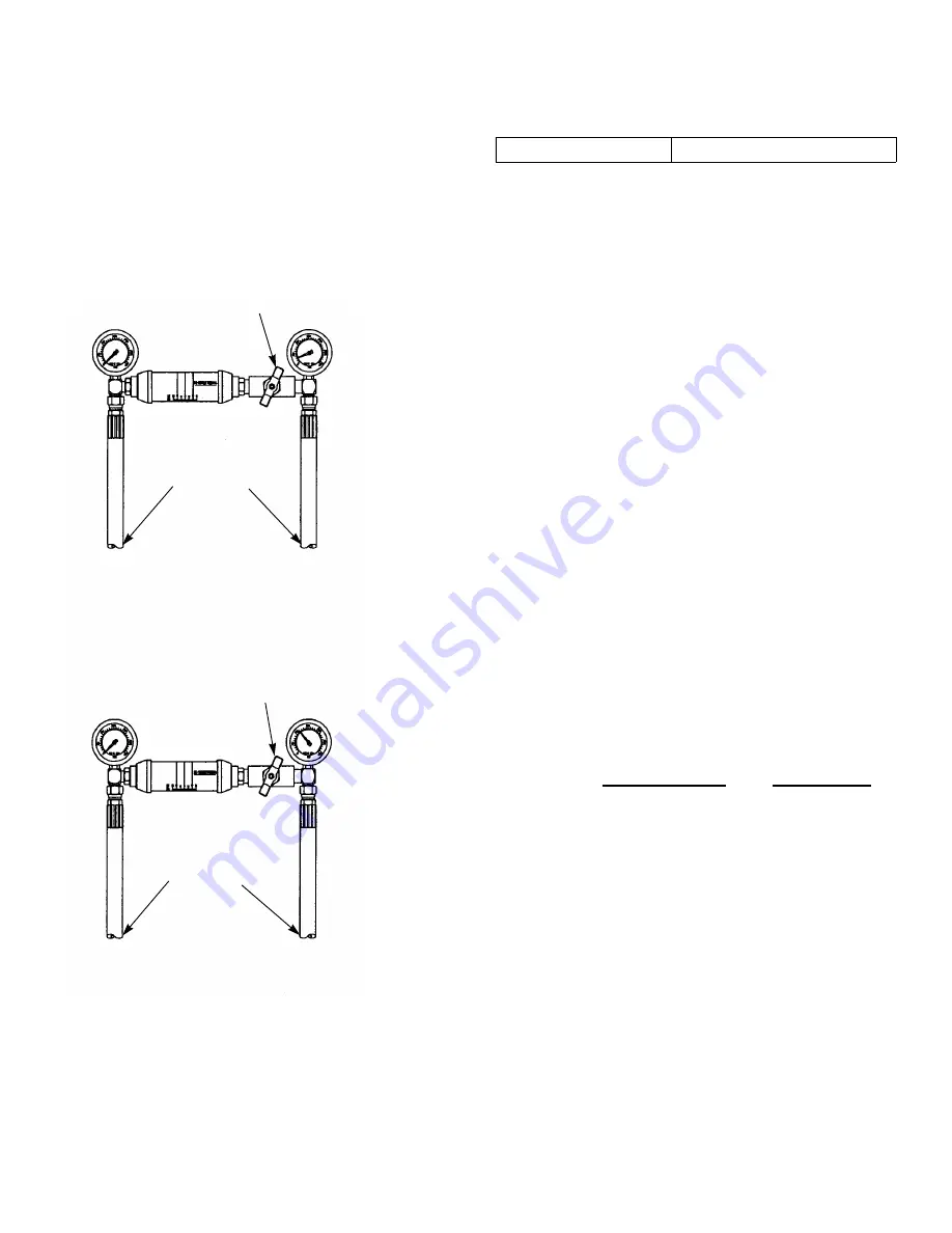
RESTRICTION VALVE
BI-DIRECTIONAL
FLOW METER
CONNECTIONS TO
THE FWD/RVS LINES
DISCONNECTED
FROM WHEEL MOTOR
CONNECTIONS TO
THE FWD/RVS LINES
DISCONNECTED
FROM WHEEL MOTOR
RESTRICTION VALVE
BI-DIRECTIONAL
FLOW METER
Содержание Series X
Страница 4: ...c 2 108936BD_ 0812 Troubleshooting 10 1...
Страница 6: ...REV E 2 2 108936BD_0812...
Страница 10: ...REV E 3 4 108936BD_0812...
Страница 12: ...REV E 4 2 108936BD_0812...
Страница 30: ...REV E 7 6 108936BD_0812...
Страница 31: ...108936BD_0812 8 1 REV E ELECTRICAL Electrical Schematic Briggs Stratton...
Страница 32: ...REV E 8 2 108936BD_0812 Electrical Schematic Kawasaki...
Страница 33: ...108936BD_0812 8 3 REV E Electrical Schematic Kohler...
Страница 34: ...REV E 8 4 108936BD_0812...
Страница 38: ...REV E 9 4 108936BD_0812...


