REV E
5-6
108936BD_0812
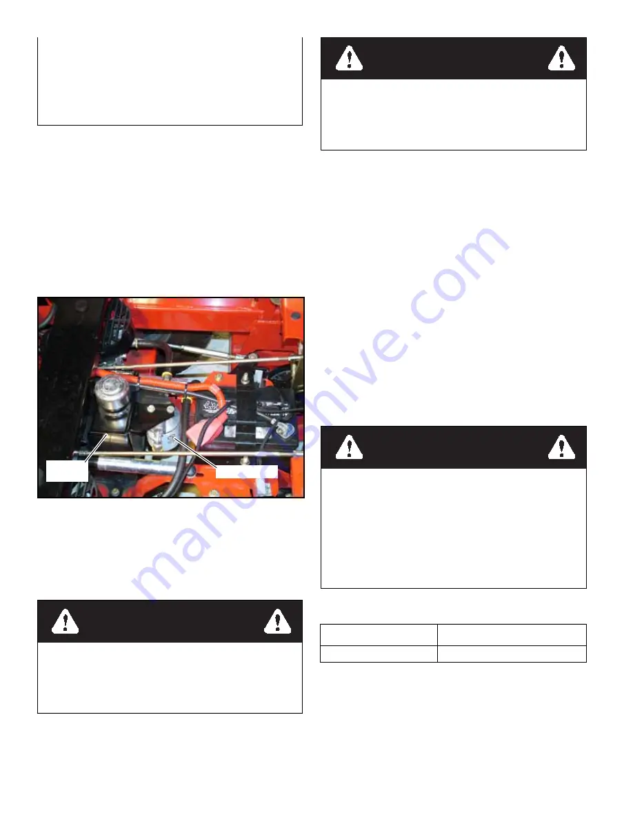
Check oil level in hydraulic system after every 50 hours of
operation or weekly, whichever occurs first. Check more often if
system appears to be leaking or otherwise malfunctioning.
Fluid level should be 1” (2.54cm) from top of reservoir. Use
only SAE 20W50 SL/SM service motor oil. Figure 5-15
Change hydraulic system filter element and oil after first 50
hours of machine operation, then replace filter and oil in reser-
voir every 500 hours thereafter. Figure 5-15
The system filter is located in front of the hydraulic reservoir.
A standard oil filter wrench is used to change filter, threads are
right handed.
Use a BigDog
®
Mowers approved filter element
only.
Prefill the filter element with clean oil, before installing,
to prevent drawing air into the system pump.
Hydraulic Pump Flow Test
The design purpose of the Bi-Directional Flow Test Kit is to
allow the customer to isolate the pump from the wheel motor
and determine if the pump is acceptable. The following informa-
tion can be used to install and test the pump by simulating a
wheel motor load.
Installation & Testing Procedures
Disconnect the system hoses at the wheel motor, or system
hoses from the pump and connect the Bi-Directional Flow Test
Kit. (Special care should be taken to prevent contamination
debris from entering pump or wheel motor system ports).
NOTE:
Using the Bi-Directional Flow Test Kit, determina-
tion of directional flow is not necessary. The flow meter may be
connected in either direction into the forward and reverse high
pressure system lines.
NOTE:
The following adapter fittings will be required when
connecting the Bi-Directional Test Kit (Excel P/N 783886 or
Hydro-Gear P/N 70661):
PK (12) Series Pumps require two 771311 adapter
fittings.
CAUTION:
Ensure all fittings and hoses are attached
securely. This test is being completed on the vehicle’s high pres-
sure system lines. Failure to perform this properly could result
in bodily injury.
Testing Procedures
1.
Use approved jack stands to raise the drive wheels off the
floor.
2.
Open the restriction valve all the way.
3.
Bring the engine to maximum operating speed.
CAUTION:
Damage to the flow meter and/or re-calibration
may result from testing at input speeds that exceed the above
recommendations.
4.
For the pump being tested, move the steering control
levers in full forward motion. (It will be necessary to lock
the steering control levers into full forward position to
prevent false readings).
5.
Operate without any load for approximately 30 seconds
to 1 minute. This allows the system oil temperature to
Before applying pressure to hydraulic system, make sure
all connections are tight and all hoses and lines are in
good condition. To find a leak under pressure, use a piece
of cardboard or wood —
never
use your hands. Relieve
all pressure in the system before disconnecting or work-
ing on hydraulic lines. To relieve pressure, lower all
attachments and shut off engine.
Figure 5-15
WARNING
Certain procedures require the vehicle engine to be
operated and the vehicle to be raised off of the ground.
To prevent possible injury to the servicing technician
and/or bystanders, insure the vehicle is properly
secured.
Hydraulic filter
Hydraulic
reservoir
WARNING
Do not attempt any adjustments with the engine run-
ning. Use extreme caution while working in or around
all vehicle linkage! High temperatures can be gener-
ated. Follow all safety procedures outlined in the vehi-
cle owner’s manual!
WARNING
Never work under the machine or attachment unless it is
safely supported with jack stands. Make certain machine
is secure when it is raised and placed on the jack stands.
The jack stands should not allow the machine to move
when the engine is running and the drive wheels are rotat-
ing. Use only certified jack stands. Use only appropriate
jack stands, with a minimum weight rating of 2000
pounds to block the unit up. Use in pairs only. Follow the
instructions supplied with the vehicle stands.
Pumps
Engine full throttle rpm setting
PK (12)
3600
Содержание Series X
Страница 4: ...c 2 108936BD_ 0812 Troubleshooting 10 1...
Страница 6: ...REV E 2 2 108936BD_0812...
Страница 10: ...REV E 3 4 108936BD_0812...
Страница 12: ...REV E 4 2 108936BD_0812...
Страница 30: ...REV E 7 6 108936BD_0812...
Страница 31: ...108936BD_0812 8 1 REV E ELECTRICAL Electrical Schematic Briggs Stratton...
Страница 32: ...REV E 8 2 108936BD_0812 Electrical Schematic Kawasaki...
Страница 33: ...108936BD_0812 8 3 REV E Electrical Schematic Kohler...
Страница 34: ...REV E 8 4 108936BD_0812...
Страница 38: ...REV E 9 4 108936BD_0812...


